


Key Takeaways
- Proper check valve installation directly affects sealing reliability, service life, and system safety.
- Flow direction, orientation, and pipe alignment must be verified before commissioning
- Installation conditions influence cracking pressure, wear rates, and backflow prevention.
- Clean pipelines and correct gasket torquing can help reduce leakage and premature failure.
- Following disciplined installation practices supports long-term operational stability in critical systems.
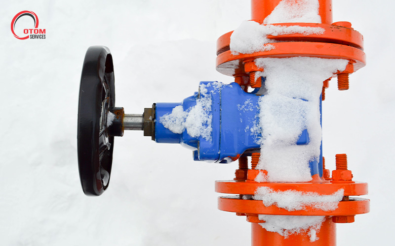
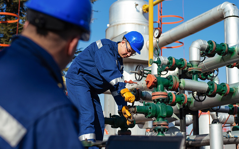
In industrial fluid systems, check valves play a critical role in maintaining process stability and protecting upstream equipment. When installed correctly, they prevent reverse flow, minimise pressure disturbances, and support safe system operation. However, even a well-specified valve can underperform if installation conditions are not properly managed.
This article outlines the key technical considerations engineers and operators should account for to ensure reliable check valve performance from installation through long-term operation.
The Consequences of Improper Valve Installation
1. Backflow and Equipment Exposure
Incorrectly installed check valves may fail to close fully or respond consistently to flow reversal. This can allow backflow to reach sensitive upstream equipment, exposing pumps and compressors to reverse pressure and mechanical stress. Over time, this increases the likelihood of seal damage, bearing wear, or unplanned shutdowns.
2. Unstable Flow and Pressure Fluctuations
Poor orientation or inadequate alignment can disrupt how the internal disc or plates respond to changing flow conditions. This may result in oscillation, delayed closure, or uneven seating, contributing to pressure instability within the system. In dynamic operating environments, these fluctuations can affect process control and overall system efficiency.
3. Accelerated Internal Wear
When check valves are subjected to misalignment, debris, or uneven loading, internal components such as seats, hinges, and discs experience abnormal wear patterns. This reduces sealing effectiveness and shortens service life, often requiring earlier inspection or replacement than anticipated.
4. Increased Maintenance and Downtime
Collectively, these issues translate into higher maintenance frequency and reduced system availability. Corrective actions taken after commissioning are typically more costly and disruptive than addressing installation quality during initial assembly.
What to Consider During Check Valve Installation
1. Confirm the Correct Flow Direction
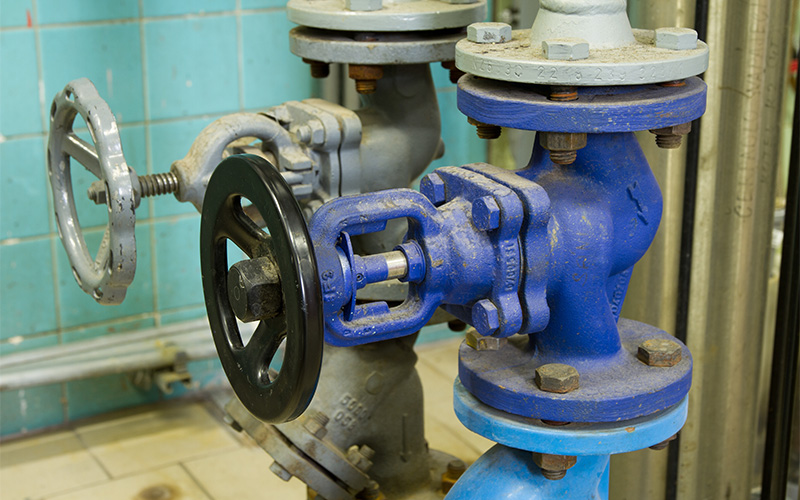
Check valves are designed for unidirectional flow, and the valve body is typically marked with an arrow indicating the intended flow path. During check valve installation, this direction must align precisely with the system flow. Verifying the orientation before final tightening ensures that the disc or plates open and close as designed, supporting consistent shut-off behaviour once the system is pressurised.
2. Choose the Right Installation Orientation
Check valves can behave very differently depending on how they are mounted within the piping system. While some designs are suitable for both vertical and horizontal installation, others rely on gravity, flow velocity, or disc balance to operate correctly. Understanding these design characteristics is essential during industrial valve setup to avoid performance issues after commissioning.
For example:
- A swing check valve generally performs best in horizontal pipelines, where gravity supports smooth disc closure. When installed vertically, unstable flow conditions may cause delayed closing, disc chatter, or incomplete seating.
- A dual-plate check valve offers a more compact and responsive design, but correct orientation remains important to ensure symmetrical plate movement and consistent cracking pressure.
Installing the valve in its intended orientation is essential for maintaining reliable sealing, predictable response, and long-term operational stability.
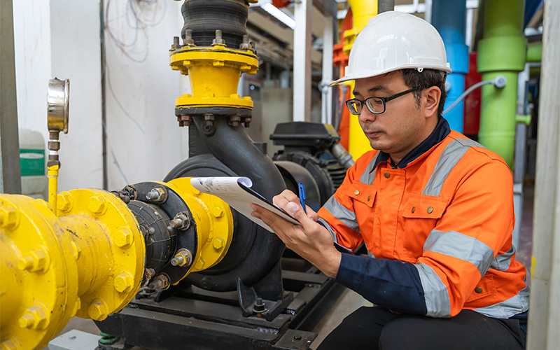
3. Ensure Proper Pipe Alignment and Support
Valves are not intended to carry external loads from piping. Misaligned flanges or unsupported pipe sections can impose bending or torsional stress on the valve body once bolts are tightened. As such, proper support is crucial during check valve installation. They carry the combined weight of the valve and adjacent piping, particularly in high-pressure or large-diameter systems.
Maintaining straight pipe runs upstream and downstream helps promote stable flow conditions and supports accurate disc movement during operation.
4. Maintain a Clean Installation Environment
Clean installation practices are particularly important in petrochemical and gas processing systems, where small particles can interfere with seating surfaces or cause scoring of internal components. Welding slag, dirt, scale, or foreign particles left in the pipeline can obstruct the valve disc or plates, preventing full closure.
Before installation, pipelines should be flushed thoroughly, and the valve interior inspected where possible. Protective end caps should only be removed immediately before installation to prevent contamination. In systems handling hydrocarbons, chemicals, or particulates, maintaining cleanliness is especially important to preserve sealing surfaces and moving parts.
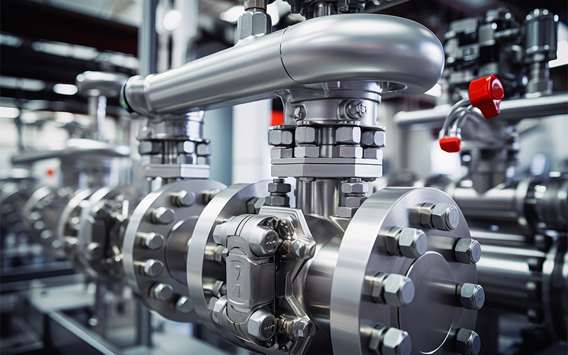
5. Apply Correct Gasketing and Controlled Bolt Tightening
Joint integrity depends on both gasket suitability and uniform bolt loading. For example, gaskets must be selected to match the system’s pressure class, temperature range, and process media. Bolts should also be tightened incrementally using a cross pattern and calibrated torque tools. This ensures even gasket compression and avoids flange distortion, supporting long-term sealing stability under operating conditions.
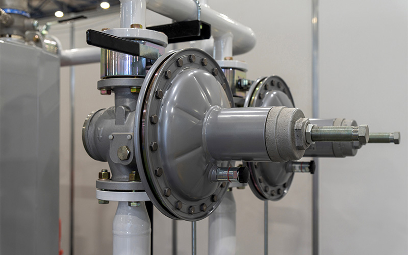
6. Account for Operating Conditions and Flow Behaviour
Check valve installation should reflect how the system will actually operate, not just static design conditions. Flow velocity, cycling frequency, and pressure variation all influence closure response. In systems prone to rapid flow reversal or surge, a non-slam check valve may be specified to reduce pressure spikes and improve operational stability. Considering these factors during installation helps align valve behaviour with broader flow control requirements.
Building Reliable Flow Control from the Start With OTOM Services
During check valve installation, ensuring correct flow direction, orientation, alignment, cleanliness, and joint integrity helps minimise operational risk and extend service life. By addressing these factors early, operators can reduce unplanned maintenance and support more stable system performance across varying operating conditions.
For industrial operators in Southeast Asia and beyond, working with a supplier that understands real operating demands adds an extra layer of assurance. OTOM Services supports oilfield, marine, and petrochemical projects by supplying valves and components suited to application requirements and providing technical post-sales guidance. For more information, contact us today.
Key Takeaways
- Diaphragm valve performance is highly dependent on material behaviour under chemical, thermal, and mechanical stress.
- No single material suits all applications. Each option presents specific strengths and limitations that must be matched to operating conditions.
- Chemical compatibility, temperature range, pressure, and cycle frequency should be assessed together to avoid premature failure.
Diaphragm valves are widely used across oil and gas, chemical processing, marine, and utility systems because they provide reliable shut-off and effective media isolation. However, their suitability for a given application depends heavily on the material used for the diaphragm. Each material responds differently to chemicals, temperature extremes, and mechanical cycling.
In this article, we examine the most commonly used diaphragm valve materials, outlining their key characteristics, performance limitations, and typical industrial applications.
5 Common Diaphragm Valve Materials
1. EPDM (Ethylene Propylene Diene Monomer)
EPDM is widely used in applications involving water-based media and moderate operating temperatures. Its strong resistance to hot water, steam, alkaline solutions, and many mild chemicals makes it well suited for utilities, HVAC systems, and wastewater treatment environments. The material’s inherent elasticity allows it to maintain consistent contact pressure against the valve seat during repeated opening and closing cycles, supporting reliable sealing over time.
However, EPDM performs best in systems with minimal hydrocarbon exposure, as contact with oils and fuels can lead to swelling and a gradual loss of mechanical strength. When selected within these operating limits, diaphragm valves made of this material offer stable performance, predictable service life, and dependable long-term operation.
2. PTFE (Polytetrafluoroethylene)
PTFE is selected primarily for applications involving aggressive or highly corrosive media. Its exceptional chemical inertness allows it to withstand strong acids, solvents, and reactive fluids that would degrade most elastomers. The material’s low-friction, non-stick surface also reduces product adhesion and contamination risk, making it suitable for chemical processing and high-purity systems.
Due to its limited elasticity compared to rubber-based materials, PTFE relies heavily on proper valve design and installation to achieve effective sealing.
3. NBR (Nitrile Rubber)
NBR is commonly used in systems where oils, fuels, and petroleum-based fluids are present. Its resistance to hydrocarbons, combined with good mechanical strength and abrasion resistance, makes it suitable for industrial equipment and fluid transfer applications. NBR also performs reliably under moderate pressure conditions where repeated valve cycling is required.
However, the material has lower resistance to ozone, ultraviolet exposure, and strong oxidising agents, which can limit its use in outdoor or chemically aggressive environments. Temperature tolerance is also more restricted than that of specialised elastomers. When applied within these constraints, this diaphragm valve material offers a practical and cost-effective solution for hydrocarbon services.
4. Silicone Rubber
Silicone rubber is valued for its ability to maintain flexibility across a wide temperature range, including both very low and elevated operating conditions. This thermal stability allows the diaphragm to retain sealing capability in applications where temperature variation would cause conventional elastomers to harden or deform. Silicone is also odourless, non-toxic, and easy to sterilise, supporting its use in pharmaceutical, food, and biotechnology processes.
Despite these advantages, silicone has limited resistance to oils, fuels, and concentrated acids, which can accelerate material degradation.
5. Viton (FKM)
Viton is a high-performance fluoroelastomer designed for chemically aggressive and high-temperature environments. It offers excellent resistance to a wide range of solvents, fuels, and industrial chemicals while retaining elasticity under sustained thermal stress. This combination supports extended service life and stable sealing performance in demanding industrial applications.
The material typically carries a higher initial cost and is not well-suited for prolonged exposure to steam, which can affect long-term durability.
Key Considerations When Selecting a Diaphragm Valve Material
Material selection for industrial diaphragm valves requires more than matching a datasheet to a process fluid. In practice, performance is shaped by how multiple operating factors interact over time.
1. Chemical Compatibility
The diaphragm is in direct contact with the process media, making chemical resistance a primary consideration. Beyond identifying whether a material is broadly “compatible”, it is important to assess concentration levels, exposure duration, and the presence of contaminants or cleaning agents. Some materials tolerate short-term exposure but degrade under continuous service, which can affect long-term sealing integrity.
2. Temperature Range and Thermal Cycling
Operating temperature influences elasticity, fatigue resistance, and ageing behaviour. Materials that perform well at ambient conditions may harden, soften, or lose resilience when exposed to sustained heat or frequent temperature fluctuations. Thermal cycling can accelerate material fatigue, particularly in systems with frequent start-stop operations.
3. Mechanical Flexibility and Cycle Life
Diaphragms undergo repeated flexing during valve operation. Materials with insufficient fatigue resistance may crack or lose sealing force over time. Applications involving high actuation frequency, pressure variation, or vibration require materials that can maintain flexibility without mechanical breakdown.
4. Pressure and Sealing Requirements
System pressure affects how the diaphragm seats against the valve body. Higher pressures may improve sealing initially, but can increase stress and wear over time. Material selection should account for both normal operating pressure and potential pressure surges to ensure stable valve sealing performance throughout the service interval.
Making Informed Material Decisions for Long-Term Reliability
Selecting the right diaphragm valve material is ultimately about aligning material behaviour with real operating conditions. Chemical exposure, temperature range, pressure variation, and actuation frequency all influence how a diaphragm performs over time. When these factors are evaluated together, material selection becomes a proactive reliability decision rather than a reactive maintenance issue.
For industrial operators, working with an experienced valve company that understands both application demands and material limitations can help reduce downtime and support safer system operation. As a trusted supplier, OTOM Services Pte Ltd provides technical guidance to ensure your valves are specified with materials suited for long-term performance in demanding environments.
Get in touch with us today.
Key Takeaways
- Designed for extremely cold conditions, cryogenic valves enable safe handling of liquefied gases used across energy, industrial, and research sectors.
- Material selection, extended bonnets, and sealing integrity are critical to performance at sub-zero temperatures.
- Different valve designs support isolation, throttling, or rapid shut-off depending on process requirements.
- Proper specification is essential for safety, compliance, and long-term operational reliability in cryogenic systems.
Operating at temperatures below –150°C presents engineering challenges that conventional components cannot withstand. Cryogenic valves are engineered specifically for such environments, where standard metals may become brittle and sealing systems can fail. Manufactured using low-temperature alloys and extended bonnet designs, these valves keep critical sealing elements away from extreme cold while maintaining pressure integrity.
Main Types of Valves Used in Cryogenic Service
Cryogenic systems rely on valves that can be adapted for operation at extremely low temperatures. While the basic operating principles remain the same, their suitability depends on how they integrate into cryogenic process requirements.
1. Ball Valves
Ball valves use a rotating ball with a precision-machined bore to provide quick, quarter-turn operation. Their tight shut-off capability and simple internal geometry make them suitable for on-off service where leakage control is critical, particularly in transfer and isolation points within cryogenic piping systems.
2. Globe Valves
Globe valves regulate flow using a linear motion disc and a stationary seat. This design allows for accurate throttling and controlled flow adjustment, which is important when managing pressure changes and gradual cooling or warming in cryogenic processes.
3. Gate Valves
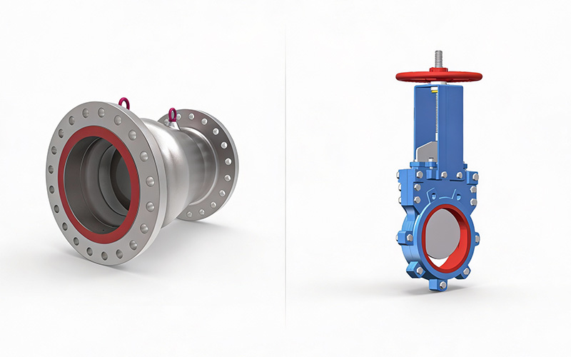
Gate valves control flow by lifting a vertical gate fully out of the flow path, providing a straight-through passage with minimal pressure drop when open. They are commonly used for isolation in large-diameter cryogenic pipelines where unrestricted flow is required.
4. Butterfly Valves
Butterfly valves use a rotating disc mounted on a central shaft to control flow. Their compact, lightweight design and fast actuation make them suitable for large pipelines and applications where space and weight constraints are important.
What Makes a Valve Cryogenic-Rated?
A valve is considered cryogenic-rated when it is designed and specified to operate reliably at temperatures below –150°C. Key requirements include:
- A defined cryogenic design temperature range
- Bonnet extensions suitable for insulated or cold-box installations
- Materials that retain toughness at low temperatures
- Seat and packing systems that accommodate thermal contraction
- Pressure class and end connections suited to low-temperature service
- Compliance with testing and inspection standards
How Valves Are Adapted for Cryogenic Service
Standard valve designs cannot operate safely at extreme temperatures without significant engineering modifications. To support reliable fluid control, critical design adaptations must be made.
1. Low-Temperature Materials
Cryogenic valve bodies, stems, and internal components are manufactured from materials that retain impact strength and ductility at extremely low temperatures. Austenitic stainless steels, aluminium alloys, and selected nickel-based alloys are commonly used to prevent embrittlement and cracking. These materials allow the valve to withstand rapid cooling, thermal cycling, and sustained exposure to cryogenic fluids without structural degradation.
2. Extended Bonnets and Stems
Extended bonnet designs increase the distance between the cryogenic fluid and the stem packing area. This design limits heat transfer to the sealing system, keeping packing materials at a higher, more stable temperature. By preventing packing from freezing or hardening, extended stems reduce the risk of stem leakage, torque increase, and loss of operability during prolonged cryogenic service.
3. Sealing and Packing Systems
Sealing systems in the valves are engineered to maintain contact pressure despite thermal contraction of metal components. To maintain reliable shut-off and leakage control, sealing and packing systems are specified to account for the following:
- Thermal contraction effects on seats and sealing surfaces, ensuring contact pressure is maintained as components shrink at low temperatures.
- Dimensional stability of the seat and packing materials, allowing seals to accommodate repeated cooling and warming cycles without degradation.
- Fugitive emissions and leakage control, particularly along the stem, through the use of low-emission packing designs where required.
- Media-specific requirements, where certain services may impose additional specifications, such as oxygen service cleaning.
These considerations help ensure consistent sealing performance, minimise leakage, and support safe operation across a wide range of cryogenic applications.
Common Applications of Cryogenic Valves
Across energy, industrial, and research sectors, cryogenic valves are deployed wherever gases must be stored, transferred, or controlled at extremely low temperatures.
1. Liquefied Gas Handling and Distribution
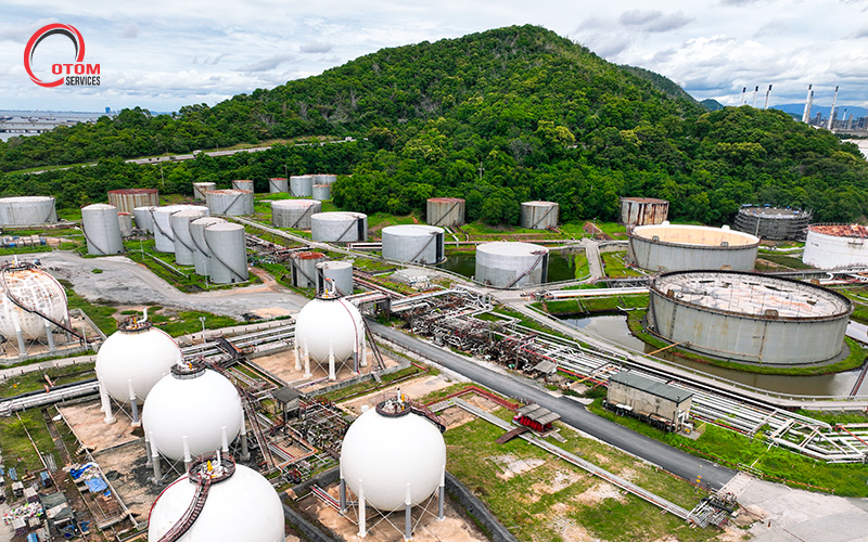
Liquefied natural gas, liquid nitrogen, and liquid oxygen are widely used across power generation, industrial manufacturing, and medical supply chains. These fluids must remain in a liquid state to be transported and stored efficiently, requiring precise isolation and transfer at consistent temperatures.
Cryogenic valves are used at critical points such as loading arms, storage tanks, transfer lines, and vaporisation systems. In these operations, reliable shut-off and controlled flow are essential to prevent unplanned vaporisation, pressure surges, or process disruption during routine operations.
2. Research, Aerospace, and Testing Facilities
Cryogenic environments are integral to aerospace propulsion testing, advanced materials research, and laboratory-scale thermal studies. In these applications, valves are subjected to frequent cycling, controlled dosing, and precise sequencing rather than continuous industrial flow.
Even minor deviations can affect test results or compromise safety protocols, making performance consistency, repeatability, and traceability critical. The valves used in these settings are typically specified to meet strict documentation, inspection, and quality control requirements.
Ensuring Precision In Critical Environments
Selecting cryogenic valves is not a one-size-fits-all decision. Different applications place different demands on flow control, isolation, and operational stability, particularly in environments involving liquefied gases and extreme temperatures. Understanding these requirements is key to avoiding performance issues and unplanned downtime.
With experience supporting oilfield, marine, and petrochemical systems, OTOM Services Pte Ltd supports clients across the full valve lifecycle. From sourcing and system integration to valve servicing and refurbishment, we help engineers and operators ensure reliable performance and long-term operational continuity in diverse environments.
Contact us today to learn more.
Key Takeaways
- When it comes to gate valves vs globe valves, understanding their core differences can help engineers choose the right solution for efficiency and reliability.
- Gate valves suit simple on off duties, while globe valves excel at precise flow regulation.
- Correct valve selection supports safer operation in high-pressure pipeline systems and reduces long-term maintenance needs.
Selecting the right valve can involve numerous factors, especially when the system must operate safely, consistently, and cost effectively. More often than not, the dilemma falls to gate valves vs globe valves, two of the most widely used industrial options. By understanding their distinct strengths, how they work and where they perform best, you can make informed decisions that support smooth operations and fewer disruptions.
1. Design and Operation
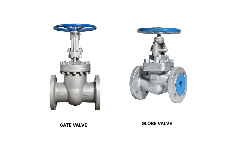
At a glance, gate and globe valves may look similar, yet their internal designs differ significantly.
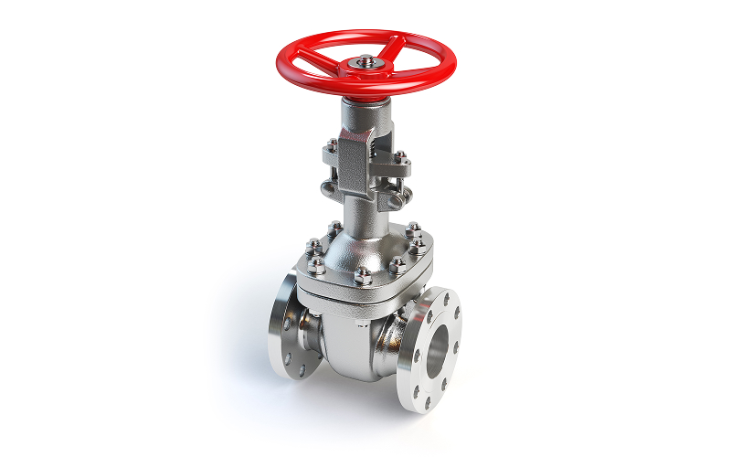
Gate valves use a flat or wedge-shaped disc that moves vertically up and down. When the gate is fully raised, flow passes straight through with little obstruction. When lowered, the gate blocks the flow completely. This simple motion makes gate valves easy to understand and operate, particularly in systems where the valve remains either fully open or fully closed for long periods.
Globe valves, on the other hand, rely on a plug and seat mechanism. The flow path changes direction inside the valve body, allowing the plug to move closer to or further from the seat. This structure enables finer control over how much fluid passes through, making globe valves a key component amongst process control valves used in regulated environments.
2. Flow Control Characteristics
Flow behaviour is often the deciding factor when considering gate valves vs globe valves.
Gate valves are ideal for on/off control. Because the flow path is straight when the valve is open, pressure loss is minimal. This characteristic is especially useful in long pipelines where maintaining flow efficiency matters. However, gate valves are not designed for throttling. Using them partially open can cause vibration and wear.
Globe valves are built for accuracy. Their design allows operators to adjust flow rates gradually and precisely. This makes them suitable for applications requiring careful isolation and regulation, such as dosing, temperature control, or balancing flows within a system. The trade off is a higher pressure drop compared to gate valves, due to the more complex internal flow path.
3. Pressure and Maintenance Considerations
Pressure conditions and maintenance expectations also influence valve selection.
Gate valves provide full-bore flow, meaning the internal diameter matches the pipeline. This reduces turbulence and simplifies inspection and cleaning, particularly in clean service environments. In demanding applications, options like a Demco gate valve are often selected for their robust construction and suitability for large diameter lines.
Globe valves are better equipped to handle higher pressure differentials. Their seat and plug arrangement can withstand significant pressure changes, but this precision comes at a cost. The seats experience more wear over time, so globe valves may require more frequent inspection and servicing to maintain performance.
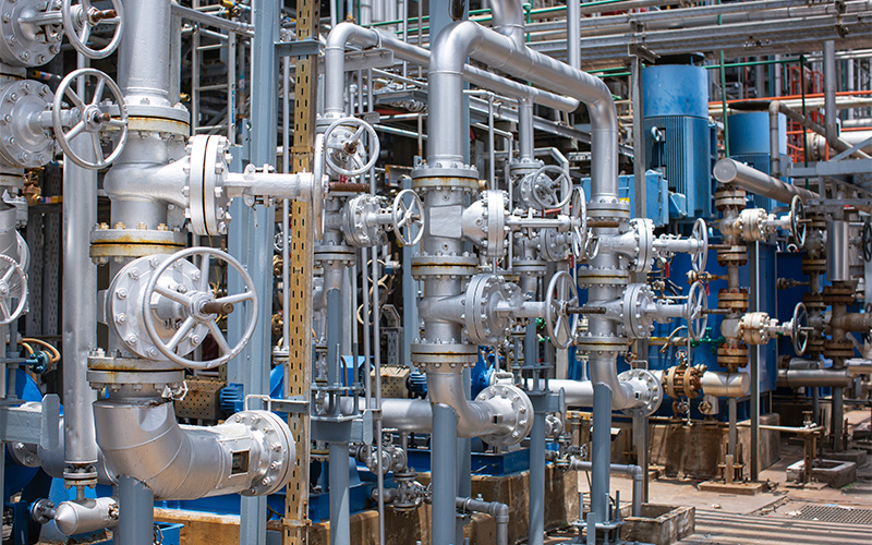
4. Industrial Applications
Each valve type has found its place across industries.
Gate valves are commonly used in pipelines, oil and gas installations, and water treatment plants. Their main role is isolation, allowing sections of a system to be shut off safely for maintenance or emergencies. For buyers comparing options from various gate valve suppliers, ease of operation and compatibility with existing pipework often guide the final choice.
Globe valves appear more often in chemical processing, power generation, and marine environments. In shipboard systems, a marine globe valve is valued for its ability to control flow accurately despite changing pressures and operating conditions.
Ultimately, the gate valve vs globe valve debate is not about finding a better or worse option, but matching each valve design to your operational needs. Gate valves offer simplicity, low pressure loss, and reliable isolation. Globe valves provide precision, control, and stability under fluctuating pressures. Understanding these differences helps engineers and operators build systems that are safer, more efficient, and easier to maintain.
At OTOM Services, we support industrial clients by supplying dependable valve solutions and technical guidance tailored to real world applications. From selection to sourcing, our team focuses on practical performance and long-term value.
To discuss your requirements or clarify the right valve choice for your system, please contact us today.
Key Takeaways
- Globe valves are designed to manage flow and pressure with precision across a wide range of systems.
- Each type of globe valve serves distinct industrial applications, depending on efficiency, layout, and operating demands.
- Selecting the right globe valve depends on understanding flow direction, pressure demands, and overall system needs.
Globe valves play a central role in many engineered systems, particularly where accurate flow control and reliable shutoff are required. Their internal design allows operators to fine-tune how fluids move through a pipeline, making them a trusted choice across sectors that depend on consistency and safety. This guide explores the main types of globe valves available today and explains how each design supports different operating requirements.
T-Pattern (Z-Type) Globe Valve
The T-pattern globe valve, often called the Z-type, is the most widely used design. Its internal structure forces the fluid to change direction twice as it passes through the valve, creating a pressure drop that supports precise throttling. This makes it especially useful in systems that experience high-pressure drops or require frequent adjustment.
Engineers often choose this design for applications where tight shutoff is essential. Although the flow path is not the most efficient, the control it offers makes it a dependable option for regulating flow in demanding environments. Amongst common types of globe valves, this design is often the starting point for general-purpose use.
Y-Pattern Globe Valve
The Y-pattern globe valve is designed to reduce resistance within the system. By angling the stem and seat at roughly 45 degrees, the valve allows fluid to pass through with fewer directional changes. This results in lower pressure loss compared to the T-pattern design.
This valve is well suited to high-temperature or high-pressure lines where efficiency matters. It balances control with improved flow performance, making it a practical solution when system energy loss must be kept in check.
Angle Globe Valve
Angle globe valves change the direction of flow by 90 degrees within the valve body. This design removes the need for an external elbow in the piping layout, which can simplify installation and reduce potential leak points.
These valves are commonly found in marine systems and wastewater treatment facilities, where space constraints and layout simplicity are important. As part of modern valves for flow control, angle globe valves help streamline piping without compromising regulation accuracy.
Straight Flow Globe Valve
Straight flow globe valves are designed to offer a more direct passage for fluid. Their internal layout minimises turbulence, making them suitable for clean fluids that require steady movement with moderate throttling.
This design supports fluid regulation systems where maintaining flow quality is as important as control. Amongst the various types of globe valves, straight flow designs are often selected for systems that prioritise reduced obstruction while still allowing measured adjustment.
Pressure-Sealed Globe Valve
Pressure-sealed globe valves are built for extreme environments. Instead of relying on traditional bolted bonnets, they use internal pressure to enhance sealing as operating pressure increases. This makes them highly reliable in power generation and refining contexts.
These valves are selected based on strict process conditions, where safety and durability are non-negotiable. Proper valve configuration in such systems ensures long-term performance under intense thermal and mechanical stress.
Understanding the differences between globe valve types helps engineers and operators make informed decisions that support efficiency, safety, and system longevity. Each design serves a distinct purpose, from handling pressure variations to simplifying piping layouts. Selecting the right valve requires a clear understanding of system demands, operating environments, and performance expectations.
Here at OTOM Services, we support clients with sourcing, specification, and technical guidance for industrial valve solutions across diverse sectors. As a trusted valve company in Singapore with extensive experience in matching valve designs to real-world operating needs, we help ensure reliability at every stage of system operation.
Contact us today to discuss your requirements and explore solutions tailored to your application.
Key Takeaways
- Gate and check valves serve fundamentally different roles in industrial fluid systems, making correct selection critical to safety, reliability, and performance.
- Gate valve vs check valve decisions should be based on control intent versus protection needs, not interchangeability.
- Gate valves support deliberate isolation, making them essential in pump-driven and pressurised systems.
- Check valves respond automatically to flow reversal and transient conditions, reducing pressure-related stress and equipment damage.
- Using these valves together in specific configurations improves system resilience, combining operational flexibility with automatic protection.
Gate and check valves are both widely used in industrial fluid piping systems, but they differ in terms of function, operation, and application. This article provides a detailed gate valve vs check valve comparison, examining how each component controls flow, responds to pressure changes, and fits into different system configurations.
What Are Gate Valves and Check Valves?
A gate valve is a manually operated valve used primarily for flow isolation. It controls flow by raising or lowering a solid gate perpendicular to the flow path. When fully open, it provides a straight-through passage with minimal pressure loss, making it suitable for applications where unobstructed flow and positive shut-off are required.
A check valve is an automatic valve designed to prevent reverse flow. It opens under forward flow conditions and closes when flow slows or reverses, protecting upstream equipment from backflow-related damage. Different types of check valves are available to suit varying pressure, flow, and installation requirements. For example, swing-check valves use a hinged disc that responds quickly to changes in flow direction, making them common in pump discharge applications.
The Key Gate Valve vs Check Valve Difference: Control vs Automatic Protection
The primary distinction in gate valve vs check valve selection lies in how each valve manages system control and protection.
Gate valves are designed for deliberate, operator-controlled actions. They are used when flow must be intentionally started, stopped, or isolated, such as during planned shutdowns, sectional pipe isolation, or commissioning activities. Their operation depends on manual or mechanical actuation, making them suitable for predictable operating conditions where response time is not critical.
Check valves serve a fundamentally different purpose. They provide automatic protection by responding directly to changes in flow direction and pressure. When forward flow is interrupted or reverses due to events such as pump trips, pressure imbalance, or sudden stoppage, the check valve closes immediately without requiring operator input. This pressure-driven response helps reduce the effects of sudden flow reversal and pressure transients without relying on operator intervention.
Combining Gate Valves and Check Valves in Fluid Systems
In many industrial systems, gate valves and check valves are used together to provide both operational control and automatic protection.
Typical Configuration
A common arrangement places the check valve closest to the pump, with a gate valve installed downstream. This allows rapid response to flow reversal while enabling operators to isolate the line for inspection or maintenance without draining the entire pipeline.
Placing the isolation valve downstream also reduces the risk of operational damage. If the gate valve is closed inadvertently, this configuration limits stress on the check valve, supporting longer service life and more stable system performance.
Flexible Adjustments for Specific Operating Conditions
Although placing the check valve upstream of the gate valve is common practice, real-world operating conditions may require different sequencing. Examples include:
1. High-Pressure or High-Temperature Services
In steam or thermal systems, gate valves may be positioned upstream to withstand initial pressure and temperature exposure, helping to protect downstream components from excessive mechanical stress.
2. Parallel Pump or Multi-Pump Header Systems
Each pump outlet is often fitted with its own gate valve so that individual pumps or check valves can be isolated for maintenance without causing reverse flow through adjacent lines.
3. Restricted or Compact Installations
In offshore modules, marine engine rooms, or tightly packed skids, valve placement may be adjusted to suit space constraints. Any deviation from standard layouts should be supported by hydraulic modelling and analysis to confirm acceptable pressure behaviour and system safety.
The Critical Importance of Correct Valve Selection
A clear understanding of gate valve vs check valve differences is essential for maintaining reliable and safe fluid systems. Gate valves provide deliberate isolation and operational control, while check valves deliver automatic protection against reverse flow and pressure-related damage. When specified correctly and used together where appropriate, they help reduce equipment stress, minimise operational risk, and support long-term system stability in demanding industrial environments.
Working with experienced check and gate valve suppliers enables project teams to translate these technical considerations into practical, application-appropriate valve solutions. At OTOM Services Pte Ltd, we offer accurate specification, dependable sourcing, and post-sales support for critical flow control components across various sectors.
Contact us today.