


Key Takeaways
- Proper check valve installation directly affects sealing reliability, service life, and system safety.
- Flow direction, orientation, and pipe alignment must be verified before commissioning
- Installation conditions influence cracking pressure, wear rates, and backflow prevention.
- Clean pipelines and correct gasket torquing can help reduce leakage and premature failure.
- Following disciplined installation practices supports long-term operational stability in critical systems.
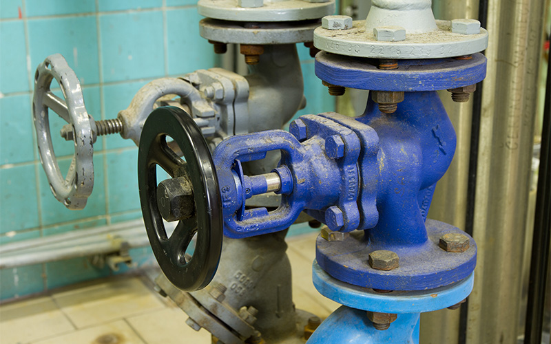
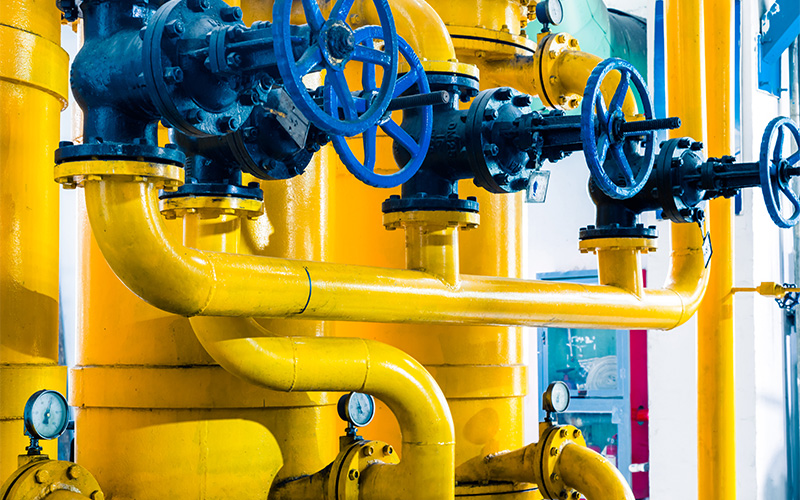
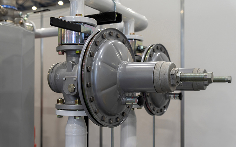
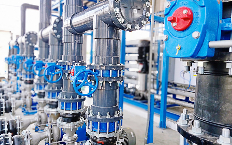
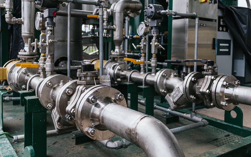
In industrial fluid systems, check valves play a critical role in maintaining process stability and protecting upstream equipment. When installed correctly, they prevent reverse flow, minimise pressure disturbances, and support safe system operation. However, even a well-specified valve can underperform if installation conditions are not properly managed.
This article outlines the key technical considerations engineers and operators should account for to ensure reliable check valve performance from installation through long-term operation.
The Consequences of Improper Valve Installation
1. Backflow and Equipment Exposure
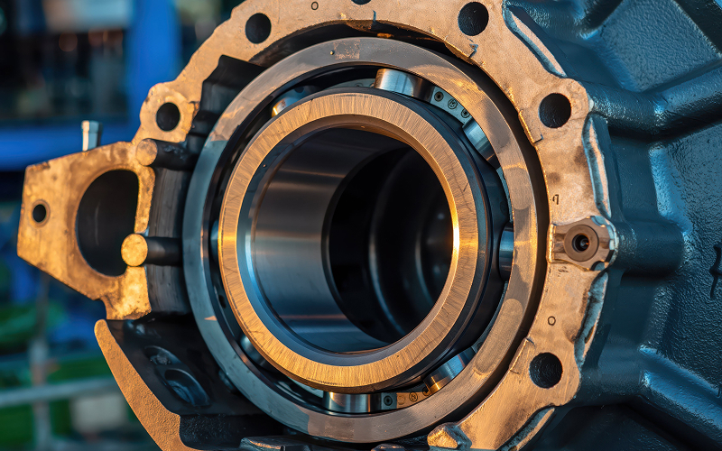
Incorrectly installed check valves may fail to close fully or respond consistently to flow reversal. This can allow backflow to reach sensitive upstream equipment, exposing pumps and compressors to reverse pressure and mechanical stress. Over time, this increases the likelihood of seal damage, bearing wear, or unplanned shutdowns.
2. Unstable Flow and Pressure Fluctuations
Poor orientation or inadequate alignment can disrupt how the internal disc or plates respond to changing flow conditions. This may result in oscillation, delayed closure, or uneven seating, contributing to pressure instability within the system. In dynamic operating environments, these fluctuations can affect process control and overall system efficiency.
3. Accelerated Internal Wear
When check valves are subjected to misalignment, debris, or uneven loading, internal components such as seats, hinges, and discs experience abnormal wear patterns. This reduces sealing effectiveness and shortens service life, often requiring earlier inspection or replacement than anticipated.
4. Increased Maintenance and Downtime
Collectively, these issues translate into higher maintenance frequency and reduced system availability. Corrective actions taken after commissioning are typically more costly and disruptive than addressing installation quality during initial assembly.
What to Consider During Check Valve Installation
1. Confirm the Correct Flow Direction
Check valves are designed for unidirectional flow, and the valve body is typically marked with an arrow indicating the intended flow path. During check valve installation, this direction must align precisely with the system flow. Verifying the orientation before final tightening ensures that the disc or plates open and close as designed, supporting consistent shut-off behaviour once the system is pressurised.
2. Choose the Right Installation Orientation
Check valves can behave very differently depending on how they are mounted within the piping system. While some designs are suitable for both vertical and horizontal installation, others rely on gravity, flow velocity, or disc balance to operate correctly. Understanding these design characteristics is essential during industrial valve setup to avoid performance issues after commissioning.
For example:
- A swing check valve generally performs best in horizontal pipelines, where gravity supports smooth disc closure. When installed vertically, unstable flow conditions may cause delayed closing, disc chatter, or incomplete seating.
- A dual-plate check valve offers a more compact and responsive design, but correct orientation remains important to ensure symmetrical plate movement and consistent cracking pressure.
Installing the valve in its intended orientation is essential for maintaining reliable sealing, predictable response, and long-term operational stability.
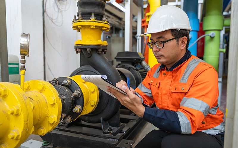
3. Ensure Proper Pipe Alignment and Support
Valves are not intended to carry external loads from piping. Misaligned flanges or unsupported pipe sections can impose bending or torsional stress on the valve body once bolts are tightened. As such, proper support is crucial during check valve installation. They carry the combined weight of the valve and adjacent piping, particularly in high-pressure or large-diameter systems.
Maintaining straight pipe runs upstream and downstream helps promote stable flow conditions and supports accurate disc movement during operation.
4. Maintain a Clean Installation Environment
Clean installation practices are particularly important in petrochemical and gas processing systems, where small particles can interfere with seating surfaces or cause scoring of internal components. Welding slag, dirt, scale, or foreign particles left in the pipeline can obstruct the valve disc or plates, preventing full closure.
Before installation, pipelines should be flushed thoroughly, and the valve interior inspected where possible. Protective end caps should only be removed immediately before installation to prevent contamination. In systems handling hydrocarbons, chemicals, or particulates, maintaining cleanliness is especially important to preserve sealing surfaces and moving parts.
5. Apply Correct Gasketing and Controlled Bolt Tightening
Joint integrity depends on both gasket suitability and uniform bolt loading. For example, gaskets must be selected to match the system’s pressure class, temperature range, and process media. Bolts should also be tightened incrementally using a cross pattern and calibrated torque tools. This ensures even gasket compression and avoids flange distortion, supporting long-term sealing stability under operating conditions.
6. Account for Operating Conditions and Flow Behaviour
Check valve installation should reflect how the system will actually operate, not just static design conditions. Flow velocity, cycling frequency, and pressure variation all influence closure response. In systems prone to rapid flow reversal or surge, a non-slam check valve may be specified to reduce pressure spikes and improve operational stability. Considering these factors during installation helps align valve behaviour with broader flow control requirements.
Building Reliable Flow Control from the Start With OTOM Services
During check valve installation, ensuring correct flow direction, orientation, alignment, cleanliness, and joint integrity helps minimise operational risk and extend service life. By addressing these factors early, operators can reduce unplanned maintenance and support more stable system performance across varying operating conditions.
For industrial operators in Southeast Asia and beyond, working with a supplier that understands real operating demands adds an extra layer of assurance. OTOM Services supports oilfield, marine, and petrochemical projects by supplying valves and components suited to application requirements and providing technical post-sales guidance. For more information, contact us today.
Key Takeaways
- Choosing the right connector supports safety, durability, and stable system performance.
- Different connector types suit different pressure levels, environments, and maintenance needs.
- Understanding connector functions helps improve long-term system reliability and planning.
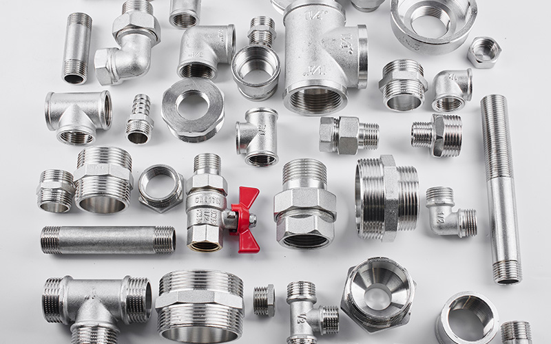
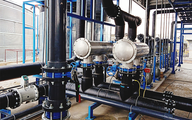
Every piping system depends on connectors to secure valves and keep fluid moving in a controlled, predictable way. Good valve connection does more than hold components together; it also influences how easily a system can be installed, inspected, maintained, and adapted over time. For anyone working with industrial, commercial, or utility piping, understanding common connector types makes decision-making far clearer and far less risky.
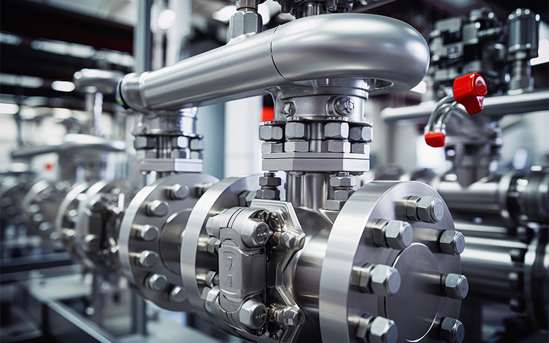
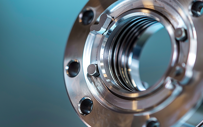
Flanged Connectors
Flanged connectors use flat rims that are bolted together with a gasket placed between them. This creates a strong, pressure-resistant seal that can also be dismantled when needed. A valve connection using flanges is often selected for systems that operate under high pressure or where regular inspection and maintenance are expected.
One advantage of flanged connectors is their reliability in larger pipe sizes. They also allow precise alignment, which supports overall mechanical joint performance. In practice, flanged connectors are commonly paired with components such as a flanged ball valve, especially in oil, gas, and industrial water systems where both strength and serviceability matter.
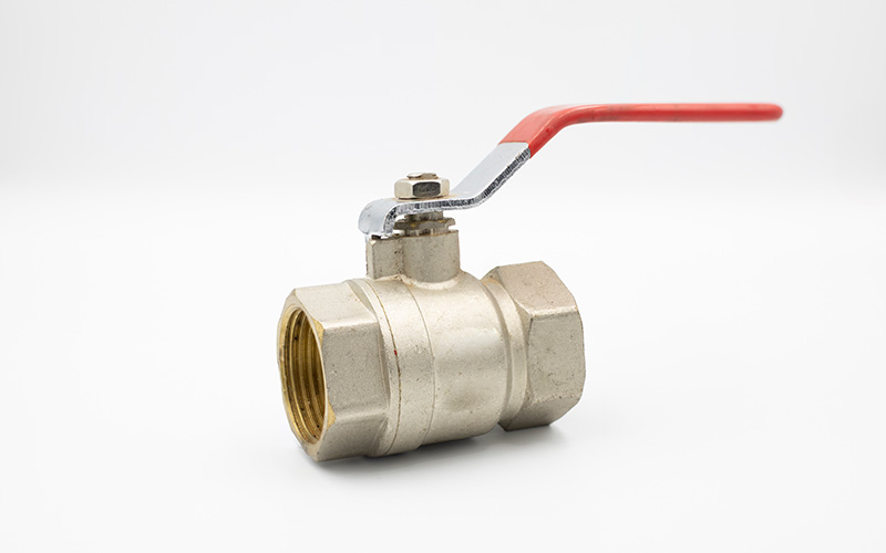
Threaded Connectors

Threaded connectors rely on matching male and female threads to join a valve to a pipe. They are straightforward to install and do not require specialised equipment, which makes them popular in low- to medium-pressure applications.
Threaded connectors are often used in smaller-diameter piping where space is limited and frequent disassembly is not expected. While threaded joints are convenient, they rely heavily on correct installation and sealing compounds to prevent leaks. For many basic systems, they remain one of the most practical pipeline connection methods available.
Welded Connectors (Butt-Weld / Socket-Weld)
Welded connectors form a permanent bond between the valve and the pipeline. Butt-weld connections join components end to end, while socket-weld connections insert the pipe into a recessed area before welding. Both methods create a continuous metal structure with excellent strength and leak resistance.
A welded valve connection is typically chosen for high-pressure or high-temperature environments where failure is not an option. Because welded joints cannot be easily dismantled, they are most suitable for systems with stable layouts and long operational lifespans. These connectors play a key role in secure valve integration within critical process lines.
Compression Connectors
Compression connectors use a nut and ferrule system that tightens around the pipe to form a seal. No welding or threading is required, which reduces installation complexity and heat exposure. This makes them especially useful in instrumentation and control lines where cleanliness and precision are essential.
In these applications, the valve connection must support accurate flow regulation without introducing contamination or stress to the tubing. Compression connectors allow fine adjustments and quick replacement, making them a preferred choice for analytical equipment and small-bore systems. They also work well with directional components such as 3-way ball valves, where precise control is required.
Grooved Connectors
Grooved connectors use a grooved pipe end, a gasket, and a coupling to form a secure yet flexible joint. This design allows for slight movement, which helps absorb vibration and accommodate thermal expansion.
A valve connection using grooved fittings is commonly found in HVAC systems, fire protection networks, and large-diameter pipelines. Installation is relatively fast, and maintenance is simplified because components can be separated without cutting or welding. Grooved connectors are often paired with equipment like butterfly valves, where space efficiency and ease of operation are important.
Selecting the right connector is a practical decision that affects safety, performance, and long-term maintenance. From flanged and threaded joints to welded, compression, and grooved options, each connector type serves a clear purpose within modern piping systems. Understanding how connectors support durability and system stability helps operators make informed choices and avoid costly issues later on.
Here at OTOM Services, we supply industrial valves and related components designed for demanding applications across marine, oil and gas, and industrial sectors. Our team focuses on reliable sourcing, technical understanding, and practical support to help clients achieve dependable system performance.
For guidance on selecting suitable valves and connectors for your application, please contact us today.
Key Takeaways
- Diaphragm valve performance is highly dependent on material behaviour under chemical, thermal, and mechanical stress.
- No single material suits all applications. Each option presents specific strengths and limitations that must be matched to operating conditions.
- Chemical compatibility, temperature range, pressure, and cycle frequency should be assessed together to avoid premature failure.
Diaphragm valves are widely used across oil and gas, chemical processing, marine, and utility systems because they provide reliable shut-off and effective media isolation. However, their suitability for a given application depends heavily on the material used for the diaphragm. Each material responds differently to chemicals, temperature extremes, and mechanical cycling.
In this article, we examine the most commonly used diaphragm valve materials, outlining their key characteristics, performance limitations, and typical industrial applications.
5 Common Diaphragm Valve Materials
1. EPDM (Ethylene Propylene Diene Monomer)
EPDM is widely used in applications involving water-based media and moderate operating temperatures. Its strong resistance to hot water, steam, alkaline solutions, and many mild chemicals makes it well suited for utilities, HVAC systems, and wastewater treatment environments. The material’s inherent elasticity allows it to maintain consistent contact pressure against the valve seat during repeated opening and closing cycles, supporting reliable sealing over time.
However, EPDM performs best in systems with minimal hydrocarbon exposure, as contact with oils and fuels can lead to swelling and a gradual loss of mechanical strength. When selected within these operating limits, diaphragm valves made of this material offer stable performance, predictable service life, and dependable long-term operation.
2. PTFE (Polytetrafluoroethylene)
PTFE is selected primarily for applications involving aggressive or highly corrosive media. Its exceptional chemical inertness allows it to withstand strong acids, solvents, and reactive fluids that would degrade most elastomers. The material’s low-friction, non-stick surface also reduces product adhesion and contamination risk, making it suitable for chemical processing and high-purity systems.
Due to its limited elasticity compared to rubber-based materials, PTFE relies heavily on proper valve design and installation to achieve effective sealing.
3. NBR (Nitrile Rubber)
NBR is commonly used in systems where oils, fuels, and petroleum-based fluids are present. Its resistance to hydrocarbons, combined with good mechanical strength and abrasion resistance, makes it suitable for industrial equipment and fluid transfer applications. NBR also performs reliably under moderate pressure conditions where repeated valve cycling is required.
However, the material has lower resistance to ozone, ultraviolet exposure, and strong oxidising agents, which can limit its use in outdoor or chemically aggressive environments. Temperature tolerance is also more restricted than that of specialised elastomers. When applied within these constraints, this diaphragm valve material offers a practical and cost-effective solution for hydrocarbon services.
4. Silicone Rubber
Silicone rubber is valued for its ability to maintain flexibility across a wide temperature range, including both very low and elevated operating conditions. This thermal stability allows the diaphragm to retain sealing capability in applications where temperature variation would cause conventional elastomers to harden or deform. Silicone is also odourless, non-toxic, and easy to sterilise, supporting its use in pharmaceutical, food, and biotechnology processes.
Despite these advantages, silicone has limited resistance to oils, fuels, and concentrated acids, which can accelerate material degradation.
5. Viton (FKM)
Viton is a high-performance fluoroelastomer designed for chemically aggressive and high-temperature environments. It offers excellent resistance to a wide range of solvents, fuels, and industrial chemicals while retaining elasticity under sustained thermal stress. This combination supports extended service life and stable sealing performance in demanding industrial applications.
The material typically carries a higher initial cost and is not well-suited for prolonged exposure to steam, which can affect long-term durability.
Key Considerations When Selecting a Diaphragm Valve Material
Material selection for industrial diaphragm valves requires more than matching a datasheet to a process fluid. In practice, performance is shaped by how multiple operating factors interact over time.
1. Chemical Compatibility
The diaphragm is in direct contact with the process media, making chemical resistance a primary consideration. Beyond identifying whether a material is broadly “compatible”, it is important to assess concentration levels, exposure duration, and the presence of contaminants or cleaning agents. Some materials tolerate short-term exposure but degrade under continuous service, which can affect long-term sealing integrity.
2. Temperature Range and Thermal Cycling
Operating temperature influences elasticity, fatigue resistance, and ageing behaviour. Materials that perform well at ambient conditions may harden, soften, or lose resilience when exposed to sustained heat or frequent temperature fluctuations. Thermal cycling can accelerate material fatigue, particularly in systems with frequent start-stop operations.
3. Mechanical Flexibility and Cycle Life
Diaphragms undergo repeated flexing during valve operation. Materials with insufficient fatigue resistance may crack or lose sealing force over time. Applications involving high actuation frequency, pressure variation, or vibration require materials that can maintain flexibility without mechanical breakdown.
4. Pressure and Sealing Requirements
System pressure affects how the diaphragm seats against the valve body. Higher pressures may improve sealing initially, but can increase stress and wear over time. Material selection should account for both normal operating pressure and potential pressure surges to ensure stable valve sealing performance throughout the service interval.
Making Informed Material Decisions for Long-Term Reliability
Selecting the right diaphragm valve material is ultimately about aligning material behaviour with real operating conditions. Chemical exposure, temperature range, pressure variation, and actuation frequency all influence how a diaphragm performs over time. When these factors are evaluated together, material selection becomes a proactive reliability decision rather than a reactive maintenance issue.
For industrial operators, working with an experienced valve company that understands both application demands and material limitations can help reduce downtime and support safer system operation. As a trusted supplier, OTOM Services Pte Ltd provides technical guidance to ensure your valves are specified with materials suited for long-term performance in demanding environments.
Get in touch with us today.
Key Takeaways
- Designed for extremely cold conditions, cryogenic valves enable safe handling of liquefied gases used across energy, industrial, and research sectors.
- Material selection, extended bonnets, and sealing integrity are critical to performance at sub-zero temperatures.
- Different valve designs support isolation, throttling, or rapid shut-off depending on process requirements.
- Proper specification is essential for safety, compliance, and long-term operational reliability in cryogenic systems.
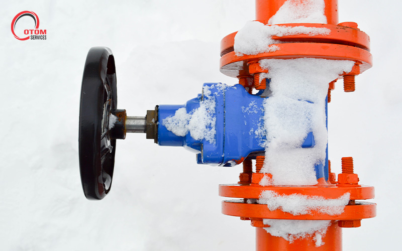
Operating at temperatures below –150°C presents engineering challenges that conventional components cannot withstand. Cryogenic valves are engineered specifically for such environments, where standard metals may become brittle and sealing systems can fail. Manufactured using low-temperature alloys and extended bonnet designs, these valves keep critical sealing elements away from extreme cold while maintaining pressure integrity.
Main Types of Valves Used in Cryogenic Service
Cryogenic systems rely on valves that can be adapted for operation at extremely low temperatures. While the basic operating principles remain the same, their suitability depends on how they integrate into cryogenic process requirements.
1. Ball Valves
Ball valves use a rotating ball with a precision-machined bore to provide quick, quarter-turn operation. Their tight shut-off capability and simple internal geometry make them suitable for on-off service where leakage control is critical, particularly in transfer and isolation points within cryogenic piping systems.
2. Globe Valves
Globe valves regulate flow using a linear motion disc and a stationary seat. This design allows for accurate throttling and controlled flow adjustment, which is important when managing pressure changes and gradual cooling or warming in cryogenic processes.
3. Gate Valves
Gate valves control flow by lifting a vertical gate fully out of the flow path, providing a straight-through passage with minimal pressure drop when open. They are commonly used for isolation in large-diameter cryogenic pipelines where unrestricted flow is required.
4. Butterfly Valves
Butterfly valves use a rotating disc mounted on a central shaft to control flow. Their compact, lightweight design and fast actuation make them suitable for large pipelines and applications where space and weight constraints are important.
What Makes a Valve Cryogenic-Rated?
A valve is considered cryogenic-rated when it is designed and specified to operate reliably at temperatures below –150°C. Key requirements include:
- A defined cryogenic design temperature range
- Bonnet extensions suitable for insulated or cold-box installations
- Materials that retain toughness at low temperatures
- Seat and packing systems that accommodate thermal contraction
- Pressure class and end connections suited to low-temperature service
- Compliance with testing and inspection standards
How Valves Are Adapted for Cryogenic Service
Standard valve designs cannot operate safely at extreme temperatures without significant engineering modifications. To support reliable fluid control, critical design adaptations must be made.
1. Low-Temperature Materials
Cryogenic valve bodies, stems, and internal components are manufactured from materials that retain impact strength and ductility at extremely low temperatures. Austenitic stainless steels, aluminium alloys, and selected nickel-based alloys are commonly used to prevent embrittlement and cracking. These materials allow the valve to withstand rapid cooling, thermal cycling, and sustained exposure to cryogenic fluids without structural degradation.
2. Extended Bonnets and Stems
Extended bonnet designs increase the distance between the cryogenic fluid and the stem packing area. This design limits heat transfer to the sealing system, keeping packing materials at a higher, more stable temperature. By preventing packing from freezing or hardening, extended stems reduce the risk of stem leakage, torque increase, and loss of operability during prolonged cryogenic service.
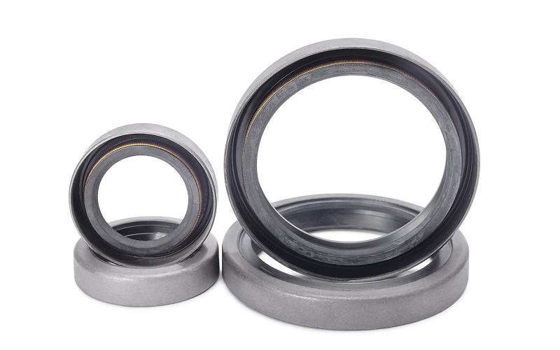
3. Sealing and Packing Systems
Sealing systems in the valves are engineered to maintain contact pressure despite thermal contraction of metal components. To maintain reliable shut-off and leakage control, sealing and packing systems are specified to account for the following:
- Thermal contraction effects on seats and sealing surfaces, ensuring contact pressure is maintained as components shrink at low temperatures.
- Dimensional stability of the seat and packing materials, allowing seals to accommodate repeated cooling and warming cycles without degradation.
- Fugitive emissions and leakage control, particularly along the stem, through the use of low-emission packing designs where required.
- Media-specific requirements, where certain services may impose additional specifications, such as oxygen service cleaning.
These considerations help ensure consistent sealing performance, minimise leakage, and support safe operation across a wide range of cryogenic applications.
Common Applications of Cryogenic Valves
Across energy, industrial, and research sectors, cryogenic valves are deployed wherever gases must be stored, transferred, or controlled at extremely low temperatures.
1. Liquefied Gas Handling and Distribution
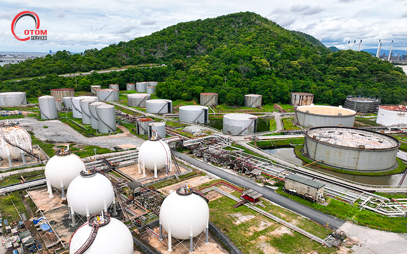
Liquefied natural gas, liquid nitrogen, and liquid oxygen are widely used across power generation, industrial manufacturing, and medical supply chains. These fluids must remain in a liquid state to be transported and stored efficiently, requiring precise isolation and transfer at consistent temperatures.
Cryogenic valves are used at critical points such as loading arms, storage tanks, transfer lines, and vaporisation systems. In these operations, reliable shut-off and controlled flow are essential to prevent unplanned vaporisation, pressure surges, or process disruption during routine operations.
2. Research, Aerospace, and Testing Facilities
Cryogenic environments are integral to aerospace propulsion testing, advanced materials research, and laboratory-scale thermal studies. In these applications, valves are subjected to frequent cycling, controlled dosing, and precise sequencing rather than continuous industrial flow.
Even minor deviations can affect test results or compromise safety protocols, making performance consistency, repeatability, and traceability critical. The valves used in these settings are typically specified to meet strict documentation, inspection, and quality control requirements.
Ensuring Precision In Critical Environments
Selecting cryogenic valves is not a one-size-fits-all decision. Different applications place different demands on flow control, isolation, and operational stability, particularly in environments involving liquefied gases and extreme temperatures. Understanding these requirements is key to avoiding performance issues and unplanned downtime.
With experience supporting oilfield, marine, and petrochemical systems, OTOM Services Pte Ltd supports clients across the full valve lifecycle. From sourcing and system integration to valve servicing and refurbishment, we help engineers and operators ensure reliable performance and long-term operational continuity in diverse environments.
Contact us today to learn more.
Key Takeaways
- Effective systems rely on fluid management to keep flow, pressure, and direction stable across complex operations.
- Proper design reduces energy use, limits safety risks, and supports consistent output quality.
- Valves play a central role by regulating flow, preventing backflow, and allowing safe maintenance.
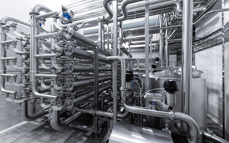
Fluid control sits quietly behind the scenes of many industrial operations, yet its impact is felt every day. From moving water through treatment plants to regulating gases in manufacturing lines, it ensures that systems run smoothly, safely, and with intent. When done well, it protects equipment, reduces interruptions, and keeps processes predictable even under demanding conditions.
What Is Fluid Control?
At its core, fluid control refers to how liquids and gases are guided through pipes, vessels, and machinery. This includes controlling flow rate, pressure levels, direction of movement, and how fluids are distributed across different parts of a system.
In practical terms, it is about making sure the right amount of fluid reaches the right place at the right time. This discipline supports safe and consistent operation across sectors such as energy, water, marine, and industrial manufacturing.
A reliable setup depends on more than a single component. Valves, actuators, sensors, and thoughtful system design work together to maintain balance. When these elements are correctly specified and aligned, flow becomes a stabilising force rather than a source of risk.
Why It Matters
Ensures System Efficiency and Energy Savings
Well-designed fluid control reduces unnecessary resistance within a system. Pumps and compressors work more efficiently when flow paths are smooth and pressures are properly managed. Over time, this lowers energy consumption and helps equipment operate closer to its intended performance range. In larger facilities, even small efficiency gains can translate into meaningful cost savings.
Prevents Operational Failures and Safety Risks
Industrial environments often involve high pressures, elevated temperatures, or hazardous media. Sudden pressure changes or uncontrolled flow can damage equipment or create unsafe conditions. Stable pressure control mechanisms help prevent leaks, mechanical stress, and unexpected shutdowns, protecting both assets and personnel.
Supports Process Accuracy and Product Quality
Many industries depend on precision. Chemical dosing, cooling cycles, and filtration processes all require steady, repeatable flow. Consistent flow management supports accuracy, helping processes remain within tolerance and reducing variability that could affect product quality. This is especially important in operations where compliance and consistency are non-negotiable.
How Valves Are Used in Fluid Control
Valves act as the decision points within a system, determining how fluids move and when they stop.
Regulating Flow and Pressure
Control valves adjust how much fluid passes through a line, helping operators maintain stable conditions. For example, a gate valve is often used where full, unobstructed flow is required, while butterfly valves offer compact, efficient regulation in larger diameter pipelines. Each type is selected based on application needs, space constraints, and operating conditions.
Preventing Backflow and Protecting Equipment
Check valves and similar devices prevent reverse flow that could damage pumps or contaminate lines. By stopping fluids from moving in the wrong direction, these components preserve system balance and reduce wear on critical equipment.
Isolating and Directing Fluid Paths
Maintenance and system changes are unavoidable. Valve isolation systems allow specific sections to be shut off without halting the entire operation. Multi-port designs also make it possible to redirect flow as processes change, supporting flexible and resilient industrial flow management.
Fluid systems rarely attract attention when they are working properly, yet their reliability depends heavily on thoughtful design and component selection. By regulating flow, maintaining pressure stability, and enabling safe maintenance, fluid control is vital in ensuring efficiency, safety, and process consistency across industrial applications.
As a specialised valve company in Singapore, OTOM Services supports industries with a focused range of valves and flow solutions tailored to demanding operating environments. Our experience spans multiple sectors, helping clients select components that align with real-world conditions.
If you are reviewing your system design or planning an upgrade, now is a good time to take a closer look at how your flow systems are performing. Contact us to explore solutions built for long-term reliability.
Key Takeaways
- The right gasket choice supports consistent sealing across pressure, temperature, and operating cycles.
- Poor material compatibility accelerates wear, leakage, and unplanned downtime.
- Understanding application conditions helps extend equipment life and reduce maintenance risk.
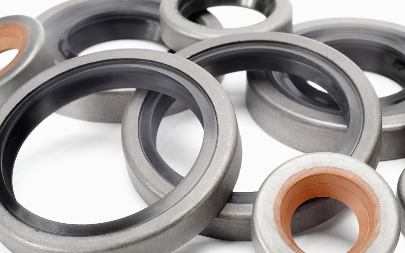
Selecting the correct gasket material is one of the most crucial decisions engineers and maintenance teams can make, yet it is often underestimated. A gasket sits quietly between flanges, but its role is anything but minor. Material choice directly influences industrial sealing performance, affecting how well a joint holds under heat, pressure, chemicals, and repeated mechanical stress. When the wrong option is used, even a well-designed system can suffer leaks, damage, or early failure.
Temperature Resistance Determines Material Stability
Heat exposure is one of the first factors to consider when choosing a gasket material. Each material responds differently as temperatures rise or fluctuate. Elastomers such as rubber perform reliably in moderate temperature ranges, offering flexibility and ease of installation. However, prolonged exposure to high heat can cause them to harden, crack, or lose elasticity.
For elevated temperatures, materials like graphite or metal-based gaskets provide better thermal stability. They retain structure where softer materials would degrade. Temperature mismatch often results in gradual seal failure rather than sudden breakdown, making it harder to detect until leaks become visible.
Chemical Compatibility Prevents Degradation
Fluids flowing through a system interact constantly with the gasket surface. Oils, acids, solvents, fuels, or seawater can all affect material behaviour. A gasket material that is not chemically compatible may swell, soften, or break down, even if temperature and pressure ratings appear suitable.
PTFE and similar chemically resistant materials are often selected for aggressive media because they resist reaction and maintain dimensional stability. Evaluating chemical exposure alongside temperature helps address key gasket durability factors before problems arise in service.
Compression and Recovery Influence Long-Term Sealing
A gasket must compress enough to fill surface irregularities and then recover when loads change. This balance is central to reliable sealing. A poorly chosen gasket material may compress initially but fail to rebound after pressure cycles, leading to permanent deformation known as creep.
Over time, creep reduces contact stress, allowing leaks to develop even though bolts remain tight. Materials with good resilience support long-term sealing by maintaining contact pressure as operating conditions vary.
Pressure Handling Impacts Safety and Performance
Pressure places direct mechanical load on a gasketed joint. Low-pressure systems can rely on softer materials, but higher pressures demand more robust solutions. High-pressure gasket materials are designed to resist extrusion and maintain integrity under sustained load.
In critical applications, a RTJ gasket is often used. This type of seal relies on controlled deformation between precision-machined flanges, providing reliable sealing where pressures are extreme. Incorrect pressure ratings increase the risk of blowouts, leaks, or flange damage.
Surface Finish Compatibility Supports Optimal Sealing
Flange surface finish plays a quiet but important role in sealing success. Some gaskets are engineered to conform to rougher surfaces, while others perform best against smooth, machined faces. A metal ring gasket, for example, requires precise flange grooves to seat correctly and achieve the intended seal.
Matching material characteristics to flange condition avoids over-compression, uneven loading, and premature wear. This step is often overlooked but has a direct effect on seal reliability.
Seal reliability depends on understanding how material properties interact with real operating conditions. Temperature resistance, chemical compatibility, compression behaviour, pressure handling, and surface finish all influence how a gasket performs over time. Choosing the right gasket material supports safer operations, longer equipment life, and fewer disruptions.
OTOM Services supplies industrial valves, gaskets, and sealing solutions for demanding applications across oil and gas, marine, and industrial sectors. The team supports material selection based on operational requirements, standards, and system conditions, including specialised options like API ring gaskets.
For guidance on selecting suitable gasket solutions for your system, please contact us to ensure that your sealing approach supports long-term performance and reliability.