


Key Takeaways
- Gaskets and seals are designed for different mechanical roles and are not interchangeable within industrial systems.
- Gaskets are used in static connections where sealing is achieved through sustained compression, while seals are required for dynamic interfaces involving movement.
- Once the sealing type is established, operating pressure, temperature, process media, and duty cycle guide design and material selection.
- Correct specification of sealing components helps reduce leakage risk and extend equipment service life. This supports safe, reliable operation in demanding industrial environments.
Introduction
When industrial systems experience leaks or pressure instability, the root cause often lies at the sealing point. Two common components used to address these issues are gaskets and seals. While both types of industrial sealing technology are designed to prevent fluid escape and maintain system integrity, they serve different mechanical functions and are engineered for different operating conditions.
What Are Gaskets?
Gaskets are mechanical sealing elements installed between two stationary mating surfaces. Their role is to create a pressure-tight seal once the joint is compressed, compensating for surface irregularities. Since there is no relative movement after installation, gaskets are designed to withstand sustained compressive loads over long periods.
Common applications of gaskets include:
- Pipe flange connections in process piping systems
- Valve bonnets, covers, and inspection ports
- Heat exchangers and pressure vessels
Gaskets are typically used when reliability under pressure and temperature is critical. As such, they are often found in industries like oil and gas production, marine engineering, power generation, and chemical processing.
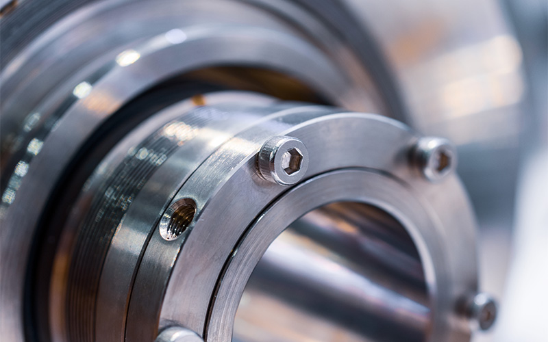
What Are Seals?
Seals are designed to maintain containment between components that experience relative motion during operation. As such, they must be able to accommodate rotation, reciprocation, or oscillation while controlling friction, wear, and heat generation.
Common applications of seals include:
- Rotating shafts in pumps and compressors
- Hydraulic and pneumatic cylinders
- Gearboxes and rotating equipment
- Mechanical assemblies
Industries such as oilfield services, marine operations, manufacturing, and petrochemical processing rely on seals to ensure long-term operational efficiency.
How to Choose the Right Gaskets and Seals
Choosing between gaskets and seals is fundamentally about understanding how the interface behaves during real operation. The following factors influence not just performance, but also reliability, maintenance demands, and failure risk.
The Main Differentiator: Static and Dynamic Sealing
The most decisive factor is whether the joint remains stationary or experiences movement during operation. Gaskets are selected for interfaces that are fixed once assembled, such as flanged pipe joints, valve covers, or pressure vessel closures. On the other hand, seals are required where components move relative to each other, such as rotating pump shafts or reciprocating hydraulic rods. Misidentifying the interface type often leads to early failure.
Factors Affecting Gasket and Seal Materials
After the nature of the interface determines whether a gasket or a seal is suitable, the specific design and material selection are influenced by operating pressure, temperature range, process media, and duty cycle.
1. Operating Pressure and Load Profile
Operating pressure influences how gaskets and seals resist deformation and maintain contact over time. In static joints, higher pressures increase the risk of gasket extrusion or blowout if the material cannot sustain the required compressive load. For example, high-pressure flange connections often specify a metal ring gasket designed to withstand extreme loads. In dynamic applications, elevated pressure increases contact forces at the sealing interface, which can accelerate wear if the seal design is not pressure-balanced.
2. Temperature Range and Thermal Cycling
Materials are selected based on their ability to maintain sealing behaviour across the full operating temperature range. Repeated heating and cooling can reduce gasket compression due to creep or relaxation, particularly in systems that cycle frequently. In such conditions, metallic ring-type joint (RTJ) gaskets are often used, as they rely on controlled plastic deformation to maintain sealing integrity at elevated temperatures.
In dynamic systems, elevated temperatures can increase friction and harden seal materials, leading to faster wear. To address this, seals made from materials with high thermal stability, low friction characteristics, and resistance to hardening are typically specified.
3. Process Media and Chemical Compatibility
Gaskets and seals must remain stable when exposed to the process media over extended periods. This is particularly relevant in systems handling hydrocarbons, solvents, or corrosive fluids. In static joints, chemical interaction can degrade gasket materials, reducing their ability to sustain compression. In dynamic systems, media properties such as lubricity or abrasiveness directly affect seal wear and friction.
4. Duty Cycle and Service Life Expectations
How often a system operates, and under what conditions, directly affects the longevity of sealing components. Static joints designed for long-term service may prioritise gasket materials that resist creep and maintain sealing stress over extended periods. For dynamic applications, the duty cycle has an even greater impact, as seals are subjected to continuous rotation, frequent start-stop cycles, or variable speeds. This is why seals with higher wear resistance, stable geometry, and predictable service life are selected to reduce unplanned downtime.
From Specification to Performance: Getting Sealing Right
Gaskets and seals play different but equally critical roles in maintaining system integrity. Selecting the appropriate sealing solution requires an understanding of how the interface behaves over time, particularly under thermal cycling, pressure fluctuations, and continuous operation. Getting this decision right helps minimise unplanned shutdowns, protect personnel and equipment, and maintain consistent process performance in demanding industrial environments.
To ensure consistency and reliability across your operations, work with OTOM Services Pte Ltd. We offer a comprehensive range of industrial components, including gaskets, seals, marine valves, oilfield equipment, and related accessories, supporting industrial applications with dependable supply and technical expertise. Speak with our team today.
Key Takeaways
- Ball valves vs needle valves differ in terms of how they regulate flow, the level of control they provide, and the types of industrial systems they are designed to support.
- Ball valves are best suited for fast shutoff, isolation, and low-restriction flow in mainline and marine systems.
- Needle valves provide precise, incremental flow control and are preferred for metering, calibration, and high-pressure instrumentation.
- Pressure rating, control accuracy, operating frequency, and maintenance expectations should guide decisions.
- Matching valve design to system requirements improves reliability, reduces wear, and supports long-term operational performance.

Valves play a critical role in determining how fluids are isolated, regulated, and measured. Among the many types available, the distinctions between ball valves and needle valves are particularly important due to their fundamentally different approaches to industrial flow control. While both are widely used across oilfield, marine, and petrochemical environments, their internal design, operating characteristics, and performance limits make them suitable for very different applications.
Ball Valves vs Needle Valves: Key Differences
1. Operational Design and Functionality
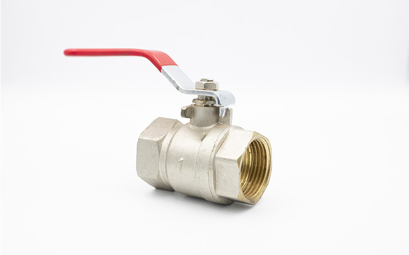
The core difference between ball and needle valves lies in their internal design. Ball valves employ a drilled spherical ball that rotates 90 degrees to align or block the flow path. This quarter-turn mechanism enables rapid, full-bore opening or closure, making ball valves ideal for isolation duties where swift response is required.
In variants such as a 3-way ball valve, the same design principle is extended to allow flow diversion or mixing between multiple ports. This provides operational flexibility while maintaining fast actuation and reliable sealing.
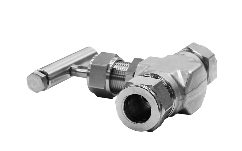
Needle valves, by contrast, use a finely threaded stem and a tapered needle that seats into a narrow orifice. Flow is adjusted through multiple turns of the stem, allowing incremental changes. This design prioritises control resolution over speed and is fundamental in applications like pressure sensing, flow measurement, and analytical sampling, where even small flow variations matter.
2. Flow Control and Accuracy
When comparing ball valves vs needle valves, flow control accuracy is a decisive factor. Needle valves offer superior modulation, enabling operators to fine-tune flow rates with high repeatability. This makes them particularly effective in metering lines, sampling systems, and calibration circuits.
On the other hand, ball valves are not designed for throttling. While they provide unrestricted flow when fully open, partial opening can lead to turbulence, seat wear, and inconsistent control. Their strength lies in on-off service rather than precise regulation, which is why they are commonly used in systems prioritising throughput over adjustability.
3. Pressure and Temperature Capability
Needle valves are typically engineered to handle higher pressures and, in many cases, elevated temperatures. Their robust stem design and tight seating geometry allow reliable performance in hydraulic systems, high-pressure instrumentation lines, and testing rigs.
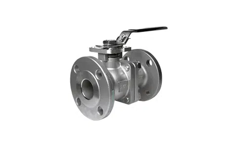
Ball valves perform best under moderate pressure and temperature ranges where tight shutoff and minimal pressure drop are required. Variants such as the flanged ball valve are widely used in industrial piping systems, featuring bolted flange connections that provide a secure, leak-resistant joint and improved structural stability.
4. Maintenance and Service Life
Ball and needle valves also differ in their maintenance considerations and service life. Ball valves are generally low-maintenance components with fewer moving parts exposed to wear. Their simple design supports long service life in general industrial environments, provided they are operated within specification.
Needle valves require more careful handling. The precision-machined needle and seat are susceptible to damage from particulate contamination or improper operation. Regular inspection and controlled actuation are necessary to maintain performance, especially in high-pressure or critical measurement systems.
Differences in Industrial Applications and Use Cases
Given their operational, control, and performance differences, ball valves and needle valves are suited to different applications within industrial systems.
Ball valves are typically used where:
- Rapid shutoff or isolation is required, particularly in mainline and emergency isolation points
- Full-bore flow with minimal pressure drop is critical to system efficiency
- Durability and low maintenance are needed in continuous industrial service
Common use cases include pipeline isolation, chemical processing systems, and marine valve installations
Needle valves are typically used where:
- Precise, incremental flow control is required rather than on-off operation
- Small flow volumes must be regulated accurately over a wide pressure range
- Controlled pressurisation is necessary to protect downstream components
Common use cases include laboratory and analytical setups, instrumentation and sampling lines, and hydraulic and pneumatic control systems.
Conclusion: Aligning Valve Selection with Operational Demands
Selecting the right valve is a strategic engineering decision that impacts system performance over time. Comparing the characteristics and functions of ball valves vs needle valves allows engineers and procurement teams to effectively balance control accuracy, durability, and operating conditions.
For operators in Singapore’s oilfield, marine, and petrochemical sectors, partner with an experienced supplier like OTOM Services Pte Ltd to strengthen both specification accuracy and supply reliability. With our technical expertise, application-specific guidance, and industry-proven valve solutions, we help businesses reduce mis-specification risks, shorten procurement cycles, and support consistent system performance.
For more information about what we do, contact us today.
Key Takeaways
- The decision between 1-piece vs 2-piece ball valves should be driven by serviceability needs, leak risk tolerance, and lifecycle expectations rather than unit cost alone.
- 1-piece ball valves minimise external leak paths and suit straightforward isolation duties where internal access is not required.
- 2-piece ball valves allow internal inspection and seal replacement, making them better suited for systems where planned maintenance is part of operations.
- 3-piece ball valves serve a different role, supporting frequent cleaning or component replacement without removing the valve from the pipeline.
- Effective valve selection aligns design configuration with process criticality, access constraints, and long-term maintenance planning.
Ball valves are widely used in pressurised fluid handling systems where fast operation and dependable shut-off are critical. While these valves are available in several designs, a common discussion centres on 1-piece vs 2-piece ball valves and which configuration best aligns with maintenance access, lifecycle cost, and system criticality.
This article provides a technical comparison of 1-piece vs 2-piece ball valves, examining differences in body construction, serviceability, and typical use cases.
1-Piece vs 2-Piece Ball Valves: Key Differences
1. Body Construction and Leak Path Considerations
The most fundamental difference between the two types of ball valves lies in their body construction and configuration.
A 1-piece ball valve is manufactured as a single, monolithic body. With no body joints or bolted connections, the design inherently minimises external leak paths. This makes 1-piece valves ideal for low-risk services where simplicity and compactness are priorities. Fewer joints also reduce the potential for loosening under vibration or thermal cycling.
In contrast, a 2-piece ball valve consists of a main body and a threaded or bolted end cap. This introduces an additional body joint that must be sealed effectively. While modern machining and gasket technologies significantly reduce the risk of leakage, the joint remains a design consideration in higher-pressure or safety-critical systems.
2. Serviceability and Maintenance Implications
1-piece ball valves are not designed to be disassembled, and their internal components, such as seats and seals, are permanently enclosed within the body. As a result, these valves are typically treated as disposable components. However, in cases where internal wear, erosion, or contamination affects shut-off performance, replacement is often the most practical solution rather than repair.
By comparison, 2-piece ball valves allow one body section to be removed, providing access to the ball, seats, and seals. This design supports inspection, cleaning, or seal replacement in principle, although in many real-world installations, the valve may still need to be removed from the line to carry out maintenance safely and effectively.
Even so, the ability to service internal components generally supports a more structured valve maintenance approach, making 2-piece valves better suited to mid-criticality services where planned intervention is preferable to full replacement.
3. Cost, Weight, and Space Considerations
1-piece valves are generally lighter, more compact, and lower in unit cost. Their reduced material usage and simpler manufacturing process make them economical for utility services, secondary lines, and non-hazardous media. Additionally, their compact form also benefits installations with limited space, such as skid-mounted equipment.
On the other hand, 2-piece ball valves are slightly heavier and more expensive due to additional machining and sealing components. However, this incremental cost is often offset by longer service life and reduced replacement frequency in demanding environments.
In applications involving larger line sizes or higher pressure ratings, 2-piece designs are more commonly supplied as flanged ball valves. These support improved load distribution, installation stability, and alignment control in rigid piping systems.
4. Performance and Safety Requirements
When evaluating the performance of 1-piece vs 2-piece ball valves, safety and compliance requirements should be considered alongside mechanical design.
For services involving hydrocarbons, elevated temperatures, or fire exposure, specifications may call for a fire-safe ball valve design. These valves are engineered with fire-resistant sealing features and a secondary sealing mechanism (often involving metal-to-metal sealing surfaces and fire-resistant stem sealing) to limit leakage and maintain shutoff capability if primary soft seats are damaged by heat.
Similarly, applications requiring flow diversion or multi-port control often extend beyond standard 2-way valves. In these cases, configurations such as a 3-way ball valve are typically produced in multi-piece constructions, which support precise internal porting, assembly, and, where required, service access.
Where Does a 3-Piece Ball Valve Fit In?

In addition to 1-piece and 2-piece ball valves, 3-piece designs occupy a different role. They consist of two end caps and a removable central body section, allowing the entire internal assembly to be removed while the end connections remain fixed in the pipeline. For systems that demand frequent cleaning, inspection, or component replacement, this configuration significantly reduces maintenance time and line disturbance.
Industries with strict cleanliness or contamination controls, such as chemical processing or hygienic fluid handling, often favour 3-piece valves for this reason. The modular design also supports a wider range of seat materials and seal options, enabling precise matching to media compatibility and operating conditions.
However, the added complexity, size, and cost often mean that 3-piece valves are typically reserved for specialised duties rather than general isolation.
Conclusion: Selecting the Right Ball Valve for Long-Term Reliability
The distinction between 1-piece, 2-piece, and 3-piece ball valves is most relevant at the specification stage, where design choices directly influence risk exposure, maintenance access, and long-term performance. Each configuration serves a different operational profile, and evaluating these differences early helps ensure valve selection remains aligned with system demands throughout its service life.
Working with an experienced supplier such as OTOM Services allows technical requirements to be addressed upfront, ensuring specifications are appropriate for operating conditions and supported by dependable product knowledge. With extensive experience supporting complex industrial systems, we provide practical guidance on valve selection, standards compliance, and application-specific considerations across a wide range of operating environments.
To learn more about what we do, contact us today.
Key Takeaways
- A check valve is a self-acting component that is essential for backflow prevention and critical equipment protection.
- It plays a vital role in maintaining pressure stability and system reliability.
- Different designs suit different flow velocities, pressures, and installation constraints.
- Knowing what a check valve is and how to choose the right component supports long-term performance in demanding industrial environments.
- Reliable sourcing and technical guidance are essential for high-risk applications.

In complex piping networks, unidirectional flow is fundamental to system safety, efficiency, and asset protection. This is where check valves come in, operating as self-acting devices that protect pumps, compressors, and piping from backflow-related damage. They are essential for maintaining pressure stability and reliable operation across industrial and marine applications.
Below, we break down what a check valve is, how it works within industrial piping systems, and why it remains a critical component across facilities.
What Is a Check Valve? Basic Functions and Operating Principles
A check valve is designed to open when upstream pressure exceeds downstream pressure, allowing fluid to move forward. The pressure difference pushes the disc or plate away from its seat and creates a clear flow path. When the flow slows or reverses, the pressure differential across the valve diminishes or reverses. The closure element then returns to its seat, sealing the passage and preventing backflow.
This operation requires no external power or manual control. The valve responds automatically to changes in flow conditions, helping maintain pressure stability and preventing reverse flow that could damage equipment or compromise system performance. In high-risk industrial environments, this self-acting behaviour plays an important role in supporting overall system reliability and process safety.
The Different Types of Check Valves
Different applications demand different valve designs, especially when flow velocity, space constraints, and pressure ratings vary.
- Swing check valve: This design uses a hinged disc that swings open with forward flow and closes under reverse flow or gravity. They are commonly applied in low-velocity pipelines such as water distribution networks.
- Wafer check valve: Wafer-type check valves feature a compact design that is widely used where installation space is limited. These fit between flanges and reduce overall system weight, making them suitable for marine and offshore installations.
- Dual-plate check valve: Made of two spring-loaded plates that close rapidly when flow reverses. This design reduces pressure spikes and is well-suited for higher-pressure flow control systems and industrial environments.
- Non-slam check valve: For systems sensitive to pressure surges, a non-slam valve provides controlled, silent closure. Its spring-assisted mechanism minimises water hammer, protecting downstream equipment in vertical or high-speed flow installations.
The Importance of Material Selection in Check Valves
Material selection is a critical engineering decision, as it directly affects performance, durability, and safety under operating conditions. Key considerations typically include:
- Fluid compatibility: Materials must resist corrosion, erosion, or chemical attack from the conveyed media, especially in oil, gas, chemical, and seawater applications.
- Pressure rating: The material must maintain structural integrity under both normal operating pressure and transient pressure surges to avoid deformation or failure.
- Operating temperature: High or fluctuating temperatures can weaken certain materials or affect sealing performance, making temperature tolerance a key selection factor.
- Mechanical strength and fatigue resistance: Repeated opening and closing cycles place stress on internal components, requiring materials that can withstand long-term mechanical loading.
By aligning material selection with these factors, engineers can improve valve reliability, extend service life, and reduce maintenance risks. This, in turn, supports more predictable system performance and fewer unplanned shutdowns.
Industrial Applications and System Protection
Check valves are widely deployed across industrial sectors where controlling flow direction is essential to protecting equipment and maintaining stable operating conditions.
1. Water Distribution and Treatment Systems
Check valves prevent reverse flow that could introduce contamination into clean water supplies. They also protect pumps and downstream equipment from reverse pressure shock during sudden shutdowns or power loss.
2. Marine and Offshore Pipelines
In ballast, bilge, and cooling water systems, check valves help stabilise flow in installations exposed to vessel movement, vibration, and changing load conditions. This reduces the risk of backflow that could disrupt system balance or damage auxiliary equipment.
3. Oil and Gas Processing Facilities
Check valves act as a protective industrial valve by shielding compressors, pumps, and pipelines from reverse flow and pressure surges. This is especially important during start-up, shutdown, or emergency conditions, where sudden flow reversal can cause mechanical damage.
Conclusion: Why Proper Selection and Expertise Matter
Selecting the wrong valve type or material creates avoidable operational risk and long-term cost exposure. A clear understanding of what a check valve is empowers engineers and operators to specify solutions that protect critical equipment and stabilise system performance. Critically, this helps reduce the likelihood of failures, downtime, and corrective maintenance, leading to safer operations and mitigated lifecycle costs over the long term.
Partnering with an experienced supplier such as OTOM Services Pte Ltd enables project teams to move beyond generic specifications and select valves that truly match real-world operating demands. With deep technical expertise across oilfield, marine, and petrochemical sectors, our team is here to support accurate specification, risk-aware selection, and reliable sourcing of critical flow control components. Learn more about our technical support and valve sourcing capabilities today.
Key Takeaways
- Butterfly valves achieve reliable flow control through a small number of precisely engineered components that work together under pressure.
- The valve body determines pressure capability, installation method, and compliance with international standards.
- Disc design and material selection directly affect flow efficiency, throttling performance, and resistance to wear or cavitation.
- The stem and its sealing interface play a critical role in torque transmission, alignment, and preventing external leakage.
- Seat material and actuator selection must match operating conditions to ensure consistent shutoff, safe operation, and long service life.
Butterfly valves are widely used across various industrial operations due to their compact footprint, fast response, and cost efficiency. While they may appear mechanically simple, their performance depends heavily on the design and interaction of individual parts.
This article provides a detailed overview of key butterfly valve components, outlining how each element supports sealing integrity, torque transmission, and operational performance.
What Is a Butterfly Valve?
A butterfly valve is a type of quarter-turn valve used to regulate or isolate fluid flow within a pipeline. It operates by rotating a disc positioned in the centre of the flow path, allowing the valve to open, restrict, or fully shut off flow with a simple 90-degree turn.
Butterfly valves are commonly used in industrial, marine, and petrochemical systems due to their compact design, low weight, and fast response. Compared to other valve types, they require less installation space and are well-suited for large-diameter pipelines where efficient flow control and ease of operation are priorities.
Key Components of a Butterfly Valve
1. Valve Body: Pressure Containment and Mechanical Support
The valve body forms the structural backbone of the assembly. It houses all internal elements and provides the interface between the valve and the pipeline. In industrial environments, bodies are commonly manufactured from ductile iron, carbon steel, stainless steel, or high-alloy materials to resist corrosion, pressure fluctuations, and external mechanical stress.
Body design also determines how the valve integrates into the piping system, with common configurations including wafer-type, lug-type, and double-flanged valves. From a systems perspective, the body is one of the most critical industrial valve components, as it directly influences pressure rating, face-to-face dimensions, and compliance with international standards.
2. Disc: Flow Modulation and Isolation Component
The disc is the primary component that modulates flow in a butterfly valve. Mounted centrally within the body, it rotates typically through 90 degrees to regulate or isolate flow. The shape and thickness of the disc influence how smoothly fluid passes through the valve, affecting flow efficiency, turbulence, and the likelihood of cavitation. This is particularly crucial when the valve is used for throttling rather than full open or closed operation.
Material selection is equally important. Stainless steel, duplex alloys, or coated carbon steel discs are often chosen to handle abrasive or corrosive media. Within the valve itself, the disc must balance structural rigidity with hydrodynamic efficiency to ensure predictable control performance.
3. Stem (Shaft): Mechanical Link Between Actuator and Disc
The stem, also known as the shaft, transmits torque from the actuator or handle to the disc. It must be accurately manufactured to keep the disc properly aligned during operation and to reduce vibration or uneven stress on internal components.
In applications where the valve operates frequently or under demanding conditions, stems are often polished, heat-treated, or coated to improve durability and resistance to corrosion. The sealing area around the stem is also designed to prevent leakage to the outside of the valve, making it a crucial part of the valve sealing mechanism. If this seal is damaged or poorly maintained, it can lead to external leakage, accelerated corrosion, and increased maintenance risk, particularly in marine and offshore environments.
4. Seat: Critical Sealing Element
The seat creates a tight seal between the disc and the valve body when the valve is closed. Its role is to prevent fluid from passing through the valve and to maintain shutoff integrity over time.
Seat materials vary depending on operating conditions. Elastomer seats are commonly used for water and low-temperature services, while polytetrafluoroethylene (PTFE) or metal seats are selected for higher temperatures, aggressive chemicals, or applications requiring fire-safe performance. Seat quality directly affects leakage performance, operating torque, and service life.
5. Actuator or Handle: Valve Control Method
The actuator (or handle) controls how the valve opens and closes. Smaller valves often use manual levers or gear operators, while larger systems rely on pneumatic, electric, or hydraulic actuators for consistent and remote operation.
Actuator selection depends on valve size, required torque, operating frequency, and system automation needs. Proper integration ensures the valve functions reliably as part of larger flow control equipment systems.
The Importance of Component Knowledge
Butterfly valves may appear straightforward in design, but their performance depends on the careful interaction of each internal component. From the valve body and disc to the stem, seat, and actuator, every element plays a role in sealing integrity and long-term reliability.
For organisations seeking dependable valve solutions, working with an experienced supplier matters. OTOM Services Pte Ltd supports critical industrial operations with access to proven valve solutions from trusted brands, such as Cameron Demco’s range of butterfly valves. With our technical guidance, you will be better equipped to specify the right valve configurations and achieve reliable long-term performance.
Contact us today to learn more.

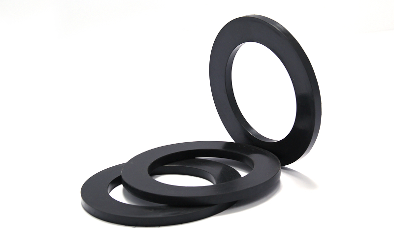
When it comes to ensuring leak-free connections in pipes and valves, ring gaskets play a vital role. Ring gaskets are commonly used in industries such as oil and gas, chemical, and manufacturing, where fluid and gas flow must be controlled efficiently. With their ability to withstand high pressure and temperature, ring gaskets are essential components in preventing leaks and maximizing operational efficiency. In this comprehensive guide, we will explore everything you need to know about ring gaskets, from their various types and materials to their installation and maintenance.
Applications of Ring Gaskets
Ring gaskets are versatile components used in a wide range of applications. Whether it’s sealing flanges, pipelines, or valves, ring gaskets provide a reliable solution for creating leak-free connections. These gaskets are typically made of materials such as metal, rubber, or graphite, depending on the specific requirements of the application.
In the oil and gas industry, ring gaskets are commonly used in flange connections. These connections are crucial for the safe and efficient transportation of oil and gas across vast distances. Ring gaskets provide a tight seal between the flanges, preventing any leakage that could result in environmental hazards or operational disruptions.
In the chemical industry, where corrosive substances are handled, ring gaskets made of chemical-resistant materials like PTFE (polytetrafluoroethylene) are used. These gaskets are designed to withstand the harsh chemicals and high temperatures often encountered in chemical processes. By preventing leaks, ring gaskets contribute to the overall safety and productivity of chemical plants.
Similarly, in the petrochemical industry, ring gaskets are essential for sealing pipelines carrying petroleum products. These gaskets ensure that no leaks occur during the transportation of volatile and flammable substances, minimizing the risk of accidents and environmental contamination.
What is a Ring Gasket?
A ring gasket is a mechanical seal that is used to fill the space between two mating surfaces, typically in flange connections. It is called a “ring” gasket because of its circular shape, which allows for an even distribution of pressure across the sealing area. The primary function of a ring gasket is to create a tight seal, preventing the escape of fluids or gases and maintaining the integrity of the system.
Ring gaskets are used in a variety of industries and equipment. In addition to flanges, they are commonly found in pipelines, valves, and other components where fluid or gas flow needs to be controlled. These gaskets are available in different sizes and materials to suit specific applications.
The importance of ring gaskets cannot be overstated. A leak in a critical system can have serious consequences, ranging from financial losses to environmental damage and even personal injuries. By providing a reliable seal, ring gaskets ensure the safety and efficiency of industrial operations.
Materials Used in Manufacturing
Ring gaskets are manufactured using a wide range of materials, each with its own unique properties and advantages. The choice of material depends on factors such as the operating conditions, the type of fluid or gas being sealed, and the required level of resistance to pressure and temperature.
Metal ring gaskets, such as those made from stainless steel or carbon steel, are commonly used in applications involving high pressure and temperature. These gaskets offer excellent resilience and can withstand extreme conditions, making them ideal for demanding environments.
Rubber ring gaskets, on the other hand, are preferred for applications where flexibility and resistance to chemicals are important. Materials like EPDM (ethylene propylene diene monomer) or Nitrile rubber provide a reliable seal and can handle a wide range of fluids, including oil, water, and gases.
Graphite ring gaskets are known for their excellent heat resistance and chemical compatibility. They are often used in high-temperature applications where other materials may fail. Graphite gaskets can withstand extreme temperatures and aggressive chemicals, making them a popular choice in industries such as petrochemical and power generation.
Conclusion
Ring gaskets are essential components in industries where leak-free connections are crucial. Their ability to withstand high pressure and temperature, combined with a variety of material options, makes them versatile and reliable sealing solutions. By selecting the right type of ring gasket and ensuring proper installation and maintenance, industries can maximize operational efficiency and safety in their fluid and gas systems.
Remember, when it comes to choosing ring gaskets, it’s essential to consult with industry experts and consider the specific requirements of your application. With the right selection and proper maintenance, ring gaskets can provide long-lasting and dependable sealing solutions for your industrial needs.
—
Note: The above article is a comprehensive guide to understanding ring gaskets and their applications. It provides general information and does not substitute for professional advice. Always consult with industry experts for specific recommendations and guidance.