


Key Takeaways
- Issues with check valves often develop gradually, with early signs that may be easily overlooked during routine operations.
- Reverse flow, vibration, abnormal noise, pressure irregularities, and external leakage are common indicators of check valve failure.
- Identifying the root causes early supports more effective diagnostics and reduces the risk of secondary equipment damage.
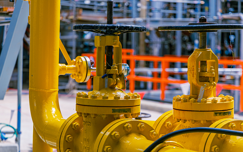
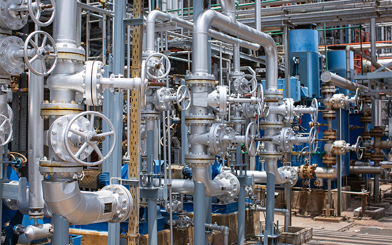
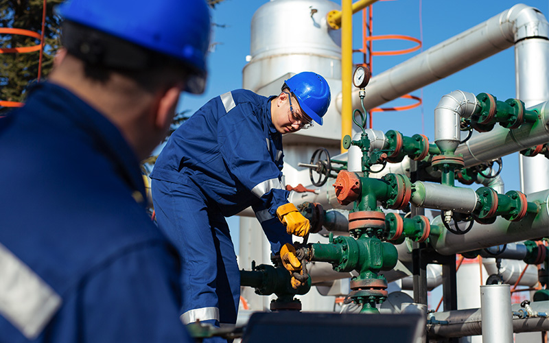
In systems handling pressurised liquids, gases, or multiphase flow, check valves are essential for maintaining directional control and safeguarding critical equipment. When performance begins to degrade, the consequences may not be immediately visible. To maintain pressure stability and avoid unplanned shutdowns, identifying the early signs of check valve failure is critical.
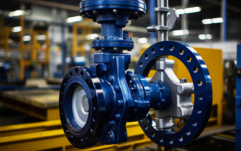
What Are Check Valves?
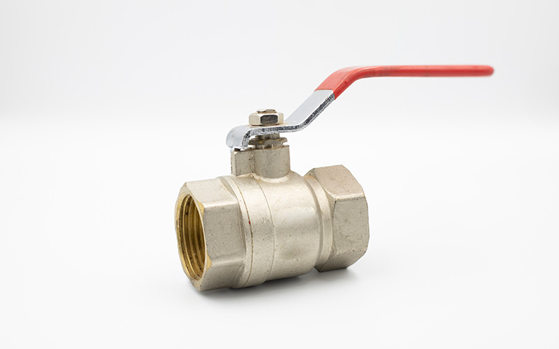
A check valve is a self-actuating device designed to allow fluid to move in one direction while automatically preventing reverse flow. Unlike isolation or control valves, it operates without external actuation, relying instead on system pressure, flow velocity, or internal spring mechanisms to open and close.
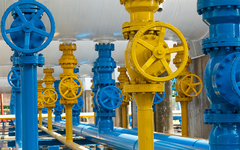
Common configurations include swing, lift, spring-assisted, and dual-plate designs, each selected based on flow characteristics, pressure conditions, and installation constraints. When functioning correctly, a check valve provides passive protection for connected equipment by maintaining flow direction and stabilising pressure behaviour within the system.
Common Signs of Performance Issues in Check Valves
1. Reverse Flow or Backflow
One of the most direct indicators of check valve failure is unintended reverse flow within the system. This condition can expose pumps, compressors, and instrumentation to mechanical stress or contamination.
Possible cause:
The valve disc, plate, or seat may be worn, fouled by debris, or unable to close fully. Erosion, corrosion, or deformation can prevent proper sealing.
What to do:
Conduct internal inspections during planned shutdowns. Maintenance teams should also remove accumulated debris, assess sealing surfaces, and replace components that no longer meet tolerance requirements. Applying structured reverse flow diagnostics can help determine whether the issue originates from valve wear, incorrect orientation, or upstream process instability.
2. Excessive Vibration or Chattering
Persistent vibration or rapid opening and closing of the check valve is another early sign of failure, particularly in high-velocity or variable-flow systems.
Possible cause:
Incorrect cracking pressure or unstable flow conditions can cause the valve to oscillate. This behaviour accelerates internal wear and may lead to fatigue damage in connected piping.
What to do:
Verify operating pressure ranges against valve specifications. Review cracking pressure requirements and installation orientation. In systems with fluctuating flow, non-slam check valves or spring-loaded check valves can help reduce slam and disc oscillation, subject to correct sizing and operating conditions. These designs use controlled closure mechanisms to limit impact forces, improving stability and reducing mechanical wear over time.
3. Unusual Noise During Operation
Abnormal sounds such as banging, clicking, or rattling during flow changes often indicate internal movement that should not be occurring under normal conditions.
Possible cause:
Loose internal components, weakened springs, or misalignment within the valve body can generate noise as parts move unpredictably.
What to do:
Isolate and depressurise the relevant section in line with site procedures, then remove the valve for inspection. Tighten, realign, or replace internal assemblies as required. Addressing unusual noise at an early stage helps prevent escalation into broader performance issues that may compromise overall system reliability.
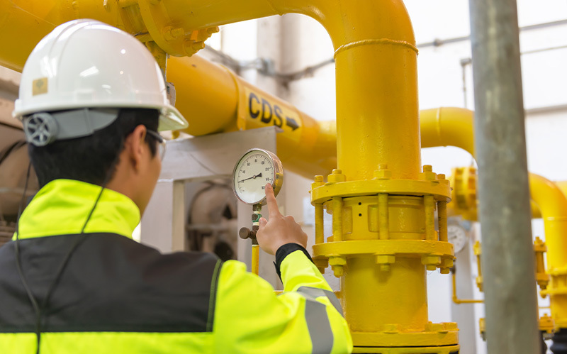
4. Pressure Drops or Irregular Flow Rates
Unexpected pressure loss or inconsistent flow behaviour may point to partial obstruction inside the valve.
Possible cause:
A damaged or partially stuck disc can restrict forward flow. Scaling, sediment, or foreign material may also impede movement.
What to do:
Clean internal passages and remove deposits to eliminate restrictions that can impede forward flow. Ensure all moving components operate freely so the valve can fully open under normal operating conditions. For higher-capacity lines, a dual-plate check valve may be suitable due to its compact design and fast, balanced closure response. Final selection should consider line size, flow characteristics, and allowable pressure loss.
5. Leakage Around the Valve Body
External leakage is another symptom of check valve failure that can result from gradual seal degradation.
Possible cause:
Ageing gaskets, degraded seals, or cracks in the valve housing can allow fluid to escape under pressure. Leakage can also occur earlier due to improper bolting, gasket selection, thermal cycling, or installation stress.
What to do:
Replace worn seals and gaskets promptly and inspect the valve body for structural damage. If cracks or deformation are detected, full valve replacement is recommended to avoid sudden rupture or safety hazards.
Potential Risks of Faulty Check Valves
1. Equipment Damage From Reverse Flow
When flow control issues are left unresolved, the effects often extend beyond the valve itself. Reverse flow can expose pumps and compressors to sudden load reversal, increasing the risk of seal damage, bearing wear, or shaft misalignment. In pressurised systems, this may also trigger pressure surges that place additional stress on pipework, flanged joints, and connected fittings.
2. Process Instability and Efficiency Loss
Faulty check valves can disrupt normal flow behaviour, leading to fluctuating flow rates and inconsistent pressure profiles. These conditions reduce overall system efficiency and increase energy consumption as equipment compensates for unintended flow changes. Over time, these issues can accelerate wear on upstream and downstream components.
3. Operational and Safety Risks
Faulty valves increase the likelihood of unplanned shutdowns, particularly during start-up or shutdown sequences when flow conditions change rapidly. Unpredictable valve behaviour during these phases can also introduce safety risks for personnel and complicate operational control, especially in high-pressure or critical service lines.
4. Increased Maintenance and Lifecycle Costs
Secondary damage caused by persistent valve malfunction often results in higher maintenance requirements and shorter equipment service life. Repairing affected pumps, piping, and instrumentation typically incurs greater cost and downtime than addressing the root issue early.
Inspecting and troubleshooting check valves regularly can help reduce these risks. This, in turn, ensures predictable system behaviour and protects critical assets across the operating lifecycle.
Conclusion: Reducing Risk Through Proactive Management
Unchecked degradation of check valves can introduce risks that extend beyond flow control, affecting equipment integrity, process stability, and operational safety. By monitoring early performance indicators and understanding their root causes, engineers and maintenance teams can intervene before minor issues escalate into costly failures.
For organisations seeking technical support, application guidance, or replacement solutions, OTOM Services Pte Ltd provides industrial expertise and equipment solutions tailored to demanding operating conditions. Engaging with an experienced supplier helps ensure that valves and components are correctly specified, installed, and maintained to support long-term operational performance. Contact us to learn more today.
Key Takeaways
- Globe valve size plays a central role in balancing flow efficiency with acceptable pressure loss in fluid systems.
- Correct sizing improves control accuracy, system stability, and long-term operational reliability.
- Considering flow demand, pressure limits, and fluid properties together leads to more predictable performance.
Fluid systems rely on balance, and when the flow is too restricted, pressure builds and efficiency suffers. Conversely, a flow that is too loose leads to unpredictable control. One component that quietly governs this balance is the globe valve, and more specifically, its size. Understanding how globe valve size affects flow efficiency and pressure drop helps operators, engineers, and decision-makers make informed choices that support stable, reliable system performance rather than costly corrections later on.
1. What Are Globe Valves
Globe valves are control valves designed to regulate fluid flow through precise throttling. Unlike simple on off valves, they allow operators to fine tune how much fluid passes through a system, making them especially useful where stability and accuracy matter.
Their internal structure features a movable plug and a stationary seat. As the plug moves closer to or further from the seat, the opening changes gradually, allowing controlled adjustment rather than abrupt flow changes. This design supports reliable shutoff while also enabling steady modulation.
Because of this, globe valves are widely used in applications that depend on consistent control, including process lines, utilities, and critical service systems. Understanding how globe valve size interacts with this internal mechanism is essential for achieving predictable results.
2. Key Factors Influencing Globe Valve Size
Selecting the correct size is not about choosing the largest valve available. It requires balancing several technical considerations so that the valve supports both flow efficiency and pressure stability.
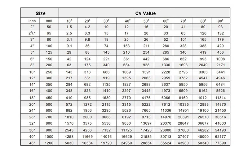
Flow Requirements and Cv Value
Every system has a required flow rate. This demand is translated into a Cv value, which indicates how much fluid can pass through the valve at a given pressure drop. If the valve Cv is too low, flow becomes restricted and pumps work harder. If it is too high, control becomes less precise. A practical valve sizing guide helps match flow demand to the appropriate Cv so the valve operates within its optimal range.
System Pressure and Allowable Pressure Drop
Pressure loss is unavoidable when fluid passes through a valve. However, excessive pressure drop reduces system efficiency and may strain upstream equipment. An undersized valve increases resistance, while an oversized valve often results in unstable control. Choosing the right size means understanding how much pressure the system can afford to lose while still operating reliably.
Fluid Properties
Fluid characteristics such as viscosity, density, and temperature directly influence sizing decisions. Thicker or denser fluids need greater flow capacity to move smoothly through the valve. Temperature changes can alter fluid behaviour and affect valve materials and sealing performance. These factors must be evaluated carefully when determining the most suitable size for a given application.
Control Accuracy Required
Some systems demand very fine modulation, where even small flow changes matter. In these cases, accurate sizing supports smoother throttling and reduces the risk of oscillation. Oversized valves tend to operate near the closed position, which can lead to erratic behaviour and poor responsiveness. Aligning valve capacity with actual operating conditions supports stable control and reinforces sound flow regulation principles.
Why Size Matters in Real Applications
In practical settings, globe valves are commonly used as industrial valves in energy, water, manufacturing, and marine systems. In shipboard piping, for example, a correctly sized marine globe valve helps maintain pressure balance across fuel, cooling, or ballast systems, contributing to safer and more efficient operation.
Similarly, specialised designs such as an angle globe valve are used where piping layout or directional flow changes require compact and efficient solutions. In each case, the sizing decision influences not only flow and pressure, but also wear rates, maintenance intervals, and overall system reliability. This highlights why globe valve size should always be considered as part of the wider system design rather than in isolation.
The relationship between globe valve size, flow efficiency, and pressure drop is fundamental to how fluid systems perform. Getting this balance right supports accurate control, protects upstream equipment, and promotes long term operational stability. By evaluating flow requirements, allowable pressure loss, fluid properties, and control expectations together, engineers and operators can make informed sizing decisions that reduce inefficiencies and avoid costly adjustments later.
Here at OTOM Services, we support these decisions by supplying and supporting a wide range of valves and related components for industrial and marine applications. As a trusted valve company in Singapore, we work closely with clients to align technical requirements with practical operating needs, from selection to ongoing support.
For guidance on selecting the right valve for your system and ensuring reliable performance, please contact us today.
Key Takeaways
- RTJ gaskets are engineered for demanding environments involving high pressure and elevated temperatures.
- Each gasket is designed to match specific pressure ranges, flange designs, and operating conditions.
- Correct selection improves sealing reliability, extends equipment lifespan, and reduces unplanned downtime.
Ring Type Joint (RTJ) gaskets play a vital role in industrial systems where failure is simply not an option. Designed for extreme pressure and temperature environments, these metal gaskets are commonly used in oil, gas, petrochemical, and marine applications. Understanding the differences between the different types of RTJ gaskets will go a long way in helping engineers, procurement teams, and maintenance planners make informed decisions that protect equipment integrity and operational safety.
Understanding Ring Type Joint Gaskets
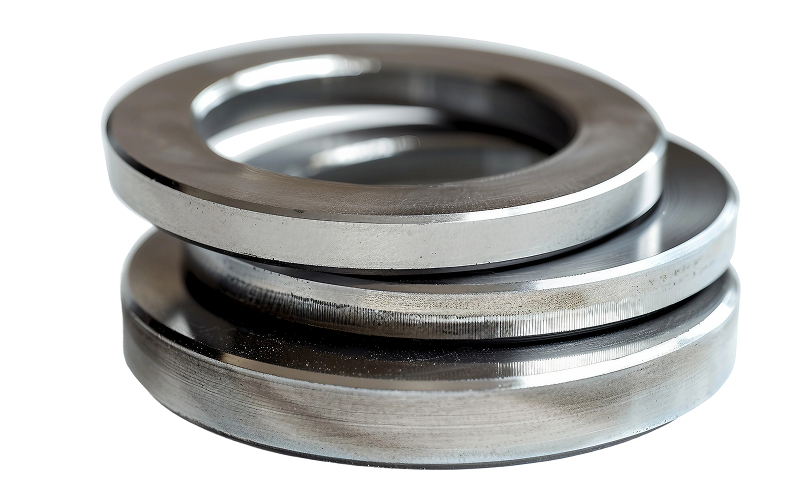
A RTJ gasket is a precision-machined metal sealing ring designed to sit within specially grooved flanges. When bolted, the gasket deforms slightly to create a tight seal capable of withstanding severe operating stresses. Compared to soft gaskets, this design delivers consistent metal gasket performance even under fluctuating temperatures and pressures.
These gaskets are commonly found in critical flange connections, including pipelines, pressure vessels, and valves where leakage could lead to safety risks or costly shutdowns. A ring joint gasket relies on exact dimensions and material compatibility to perform as intended, which is why it is important to have a good understanding of the available types of RTJ gaskets.
Types of RTJ Gaskets
1. R-Type RTJ Gasket
Design and Features
The R-type is the most widely used and cost-effective profile amongst RTJ gasket types. Available in oval and octagonal cross-sections, it fits standard flat-bottom grooves and is suitable for pressures of up to approximately 5,000 psi. Its straightforward geometry makes it easy to install and replace during routine maintenance.
Performance and Applications
R-type gaskets are commonly used in refinery equipment, pipeline systems, and pressure vessels operating under stable conditions. They provide reliable sealing without unnecessary complexity, which explains their continued popularity across general industrial services.
Material Options
Common materials include soft iron, low-carbon steel, and stainless steel, selected based on media compatibility and operating temperature.
2. RX-Type RTJ Gasket
Design and Features
The RX-type builds upon the R-type design with a pressure-energised profile. As internal pressure rises, the gasket is driven more firmly into the groove, enhancing sealing efficiency and stability.
Performance and Applications
This design makes the RX type suitable for oilfield equipment and chemical processing systems exposed to pressure cycling and vibration. It is often chosen for environments where thermal expansion and contraction are frequent.
Additional Advantages
RX gaskets are interchangeable with standard R-type grooves, allowing system upgrades without flange modification.
3. BX-Type RTJ Gasket
Design and Features
The BX-type is engineered for extreme service, handling pressures of up to 20,000 psi. Its geometry promotes metal-to-metal contact between flanges after installation, eliminating the risk of gasket extrusion or blowout.
Performance and Applications
BX gaskets are essential for offshore and subsea operations, API 6BX flanges, and critical transmission systems. They are often specified in applications involving marine valves, where absolute sealing integrity is required in corrosive and high-pressure environments.
Material Considerations
Typical materials include Inconel, alloy steel, and high-grade stainless steel for superior corrosion and temperature resistance.
Which Type Should You Choose?
Selecting from the available RTJ gasket types depends on several factors, including pressure rating, flange design, operating medium, and environmental exposure.
- R-Type: Suitable for standard pressure systems and general industrial service.
- RX-Type: Appropriate for higher-pressure systems with vibration or pressure fluctuations.
- BX-Type: Best for ultra-high-pressure, offshore, and subsea applications requiring self-sealing capability.
Careful evaluation ensures the gasket delivers reliable high-pressure sealing solutions throughout its service life.
RTJ gaskets remain a cornerstone of safe and reliable industrial sealing. By understanding how different RTJ gasket types function and where they perform best, operators can reduce leakage risks and maintain system efficiency.
OTOM Services supplies engineered sealing and valve solutions for demanding industrial and marine environments. With a focus on precision components, material compatibility, and application-specific requirements, we support clients across oil, gas, petrochemical, and marine sectors.
Contact us today to discuss your application requirements and identify the right RTJ gasket solution for your system.
Key Takeaways
- Lugged and wafer-type butterfly valves differ primarily in mounting method, isolation capability, and mechanical strength.
- A lugged-type butterfly valve supports dead-end service and sectional maintenance, making it suitable for more complex systems.
- Wafer-type valves prioritise compactness and cost efficiency for fixed, lower-load installations.
- Pressure rating, maintenance strategy, and system configuration should guide valve selection.
- Correct specification improves long-term reliability across industrial, marine, and petrochemical operations.
In industrial systems, small design choices often carry long-term operational consequences. Valve selection is one such decision, particularly when comparing wafer and lugged-type butterfly valves. While both designs serve similar flow-control functions, their structural differences influence isolation capability, maintenance planning, and mechanical performance under load.
In this article, we examine the key structural and operational differences between these two types of butterfly valves, helping operators select the most appropriate configuration for their systems.
Lugged Butterfly Valves: Designed for Isolation and Sectional Control
A lugged-type butterfly valve features threaded lugs around the valve body, allowing each side of the pipeline to be bolted independently. This design creates a more rigid connection at the flange connection, improving alignment and mechanical stability under load.
With the valve body actively supporting the pipeline, lugged designs are better able to withstand stressors like vibration, thermal expansion, or uneven loading. This makes them a preferred option in industrial environments where long-term structural integrity is a priority.
Dead-End Service and Maintenance Flexibility
One of the defining advantages of a lugged-type butterfly valve is its ability to support true dead-end service. This allows one side of the pipeline to be disconnected, isolated, or depressurised while the other side remains securely bolted and operational. In practical terms, this capability is essential for systems that require sectional isolation without shutting down the entire line.
In pipeline isolation systems, this design simplifies routine maintenance, inspection, and component replacement. It also supports phased plant expansions or retrofitting work, where new sections are added without disrupting existing operations. For facilities operating under strict safety, uptime, or compliance requirements, the ability to isolate sections reliably reduces both downtime and operational risk during maintenance activities.
Typical Industrial Applications
Lugged butterfly valves are commonly used in applications where mechanical strength, isolation capability, and maintenance access are operational priorities. Typical use cases include:
- Industrial processing lines where pipelines are subject to higher mechanical loads, vibration, or thermal expansion.
- Chemical handling systems carrying corrosive or pressurised media, where secure bolting and reliable isolation help manage safety and compliance risks.
- Marine piping systems, where a robust marine valve is required to withstand vibration, confined installation spaces, and the need for reliable sectional isolation during onboard maintenance.
Wafer-Type Butterfly Valves: Space-Efficient and Economical
Wafer butterfly valves are installed by positioning the valve body between two flanges and securing the assembly with through-bolts. The valve body does not include threaded lugs and is held in place by the clamping force generated by the flanges. This design results in a compact, lightweight valve that requires less material and occupies minimal installation space.
Pressure Behaviour and Mechanical Considerations
In wafer-type installations, mechanical loads are transferred primarily through the flange bolting rather than the valve body itself. As a result, these valves are best suited for low- to medium-pressure systems where pipeline alignment is stable and axial loads are limited. Wafer designs are not intended for dead-end service and are typically applied where full line isolation or frequent pipe disassembly is not required.
Common Use Cases in Fixed Pipeline Systems
Wafer-type butterfly valves are commonly applied in systems that prioritise compact design and installation efficiency, including:
- Water treatment and distribution networks operating under moderate pressure
- HVAC and building services where space constraints influence equipment selection
- Auxiliary utility lines, such as cooling water or secondary circulation systems
Key Selection Considerations for Engineers and Operators
1. Functional Role Within the System
Engineers should first assess the role the valve plays within the overall process. Valves intended for boundary isolation, system segmentation, or future tie-ins benefit from lugged configurations, while wafer designs are more appropriate for inline flow control within established, continuous systems. Clarifying whether the valve functions as a control point or a system boundary helps narrow the choice early.
2. Design Margins and Operating Envelope
Valve selection should account for both normal operating conditions and abnormal scenarios such as pressure surges, thermal cycling, or temporary line imbalance during shutdowns. Lugged designs provide greater tolerance where higher safety margins are required, while wafer valves perform effectively within stable, well-defined operating envelopes. Considering these margins upfront reduces the risk of over-specification or premature replacement.
3. Maintenance and Standardisation
Maintenance strategy often drives long-term cost more than the initial purchase price. Facilities with modular maintenance practices or strict isolation procedures tend to standardise on lugged designs to simplify access and reduce shutdown scope. In contrast, plants focused on minimal intervention may standardise wafer valves for uniformity and installation efficiency.
Conclusion: Selecting the Right Butterfly Valve Configuration
Choosing between wafer and lugged-type butterfly valves requires a clear understanding of how each design interacts with the wider system. Installation method, pressure demands, and maintenance planning all influence long-term performance.
For industrial operators in Singapore’s oil, marine, and petrochemical sectors, consider working with an experienced supplier such as OTOM Services Pte Ltd. We provide access to proven valve solutions, including Demco butterfly valves, supported by technical guidance to help ensure correct specification and reliable performance across demanding applications.
contact us today to learn more.
Key Takeaways
- Choosing the right connector supports safety, durability, and stable system performance.
- Different connector types suit different pressure levels, environments, and maintenance needs.
- Understanding connector functions helps improve long-term system reliability and planning.
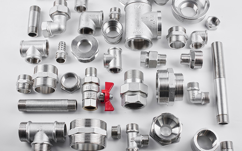
Every piping system depends on connectors to secure valves and keep fluid moving in a controlled, predictable way. Good valve connection does more than hold components together; it also influences how easily a system can be installed, inspected, maintained, and adapted over time. For anyone working with industrial, commercial, or utility piping, understanding common connector types makes decision-making far clearer and far less risky.
Flanged Connectors
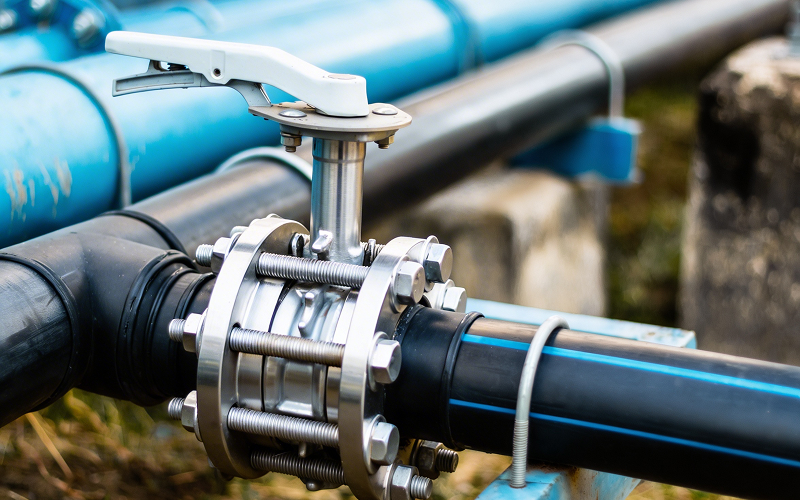
Flanged connectors use flat rims that are bolted together with a gasket placed between them. This creates a strong, pressure-resistant seal that can also be dismantled when needed. A valve connection using flanges is often selected for systems that operate under high pressure or where regular inspection and maintenance are expected.
One advantage of flanged connectors is their reliability in larger pipe sizes. They also allow precise alignment, which supports overall mechanical joint performance. In practice, flanged connectors are commonly paired with components such as a flanged ball valve, especially in oil, gas, and industrial water systems where both strength and serviceability matter.
Threaded Connectors

Threaded connectors rely on matching male and female threads to join a valve to a pipe. They are straightforward to install and do not require specialised equipment, which makes them popular in low- to medium-pressure applications.
Threaded connectors are often used in smaller-diameter piping where space is limited and frequent disassembly is not expected. While threaded joints are convenient, they rely heavily on correct installation and sealing compounds to prevent leaks. For many basic systems, they remain one of the most practical pipeline connection methods available.
Welded Connectors (Butt-Weld / Socket-Weld)
Welded connectors form a permanent bond between the valve and the pipeline. Butt-weld connections join components end to end, while socket-weld connections insert the pipe into a recessed area before welding. Both methods create a continuous metal structure with excellent strength and leak resistance.
A welded valve connection is typically chosen for high-pressure or high-temperature environments where failure is not an option. Because welded joints cannot be easily dismantled, they are most suitable for systems with stable layouts and long operational lifespans. These connectors play a key role in secure valve integration within critical process lines.
Compression Connectors
Compression connectors use a nut and ferrule system that tightens around the pipe to form a seal. No welding or threading is required, which reduces installation complexity and heat exposure. This makes them especially useful in instrumentation and control lines where cleanliness and precision are essential.
In these applications, the valve connection must support accurate flow regulation without introducing contamination or stress to the tubing. Compression connectors allow fine adjustments and quick replacement, making them a preferred choice for analytical equipment and small-bore systems. They also work well with directional components such as 3-way ball valves, where precise control is required.
Grooved Connectors
Grooved connectors use a grooved pipe end, a gasket, and a coupling to form a secure yet flexible joint. This design allows for slight movement, which helps absorb vibration and accommodate thermal expansion.
A valve connection using grooved fittings is commonly found in HVAC systems, fire protection networks, and large-diameter pipelines. Installation is relatively fast, and maintenance is simplified because components can be separated without cutting or welding. Grooved connectors are often paired with equipment like butterfly valves, where space efficiency and ease of operation are important.
Selecting the right connector is a practical decision that affects safety, performance, and long-term maintenance. From flanged and threaded joints to welded, compression, and grooved options, each connector type serves a clear purpose within modern piping systems. Understanding how connectors support durability and system stability helps operators make informed choices and avoid costly issues later on.
Here at OTOM Services, we supply industrial valves and related components designed for demanding applications across marine, oil and gas, and industrial sectors. Our team focuses on reliable sourcing, technical understanding, and practical support to help clients achieve dependable system performance.
For guidance on selecting suitable valves and connectors for your application, please contact us today.
Key Takeaways
- When it comes to gate valves vs globe valves, understanding their core differences can help engineers choose the right solution for efficiency and reliability.
- Gate valves suit simple on off duties, while globe valves excel at precise flow regulation.
- Correct valve selection supports safer operation in high-pressure pipeline systems and reduces long-term maintenance needs.
Selecting the right valve can involve numerous factors, especially when the system must operate safely, consistently, and cost effectively. More often than not, the dilemma falls to gate valves vs globe valves, two of the most widely used industrial options. By understanding their distinct strengths, how they work and where they perform best, you can make informed decisions that support smooth operations and fewer disruptions.
1. Design and Operation
At a glance, gate and globe valves may look similar, yet their internal designs differ significantly.
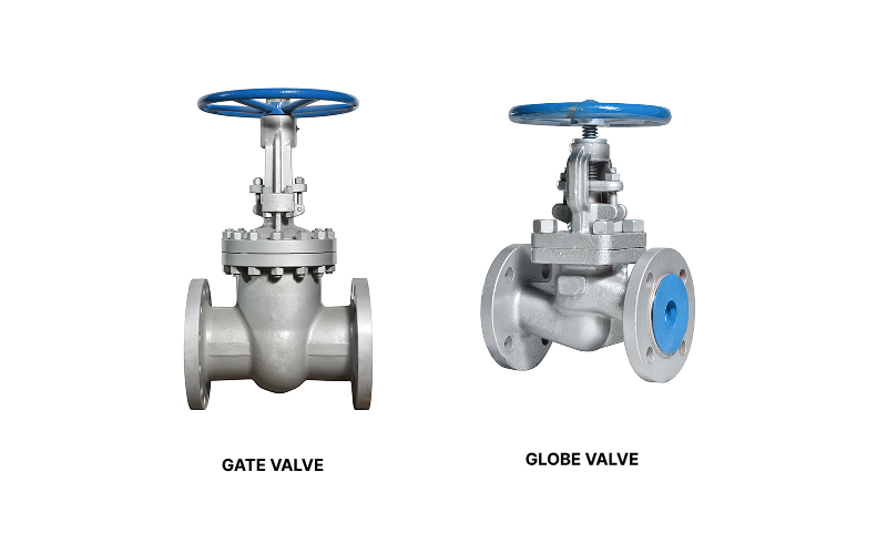
Gate valves use a flat or wedge-shaped disc that moves vertically up and down. When the gate is fully raised, flow passes straight through with little obstruction. When lowered, the gate blocks the flow completely. This simple motion makes gate valves easy to understand and operate, particularly in systems where the valve remains either fully open or fully closed for long periods.
Globe valves, on the other hand, rely on a plug and seat mechanism. The flow path changes direction inside the valve body, allowing the plug to move closer to or further from the seat. This structure enables finer control over how much fluid passes through, making globe valves a key component amongst process control valves used in regulated environments.
2. Flow Control Characteristics
Flow behaviour is often the deciding factor when considering gate valves vs globe valves.
Gate valves are ideal for on/off control. Because the flow path is straight when the valve is open, pressure loss is minimal. This characteristic is especially useful in long pipelines where maintaining flow efficiency matters. However, gate valves are not designed for throttling. Using them partially open can cause vibration and wear.
Globe valves are built for accuracy. Their design allows operators to adjust flow rates gradually and precisely. This makes them suitable for applications requiring careful isolation and regulation, such as dosing, temperature control, or balancing flows within a system. The trade off is a higher pressure drop compared to gate valves, due to the more complex internal flow path.
3. Pressure and Maintenance Considerations
Pressure conditions and maintenance expectations also influence valve selection.
Gate valves provide full-bore flow, meaning the internal diameter matches the pipeline. This reduces turbulence and simplifies inspection and cleaning, particularly in clean service environments. In demanding applications, options like a Demco gate valve are often selected for their robust construction and suitability for large diameter lines.
Globe valves are better equipped to handle higher pressure differentials. Their seat and plug arrangement can withstand significant pressure changes, but this precision comes at a cost. The seats experience more wear over time, so globe valves may require more frequent inspection and servicing to maintain performance.
4. Industrial Applications
Each valve type has found its place across industries.
Gate valves are commonly used in pipelines, oil and gas installations, and water treatment plants. Their main role is isolation, allowing sections of a system to be shut off safely for maintenance or emergencies. For buyers comparing options from various gate valve suppliers, ease of operation and compatibility with existing pipework often guide the final choice.
Globe valves appear more often in chemical processing, power generation, and marine environments. In shipboard systems, a marine globe valve is valued for its ability to control flow accurately despite changing pressures and operating conditions.
Ultimately, the gate valve vs globe valve debate is not about finding a better or worse option, but matching each valve design to your operational needs. Gate valves offer simplicity, low pressure loss, and reliable isolation. Globe valves provide precision, control, and stability under fluctuating pressures. Understanding these differences helps engineers and operators build systems that are safer, more efficient, and easier to maintain.
At OTOM Services, we support industrial clients by supplying dependable valve solutions and technical guidance tailored to real world applications. From selection to sourcing, our team focuses on practical performance and long-term value.
To discuss your requirements or clarify the right valve choice for your system, please contact us today.